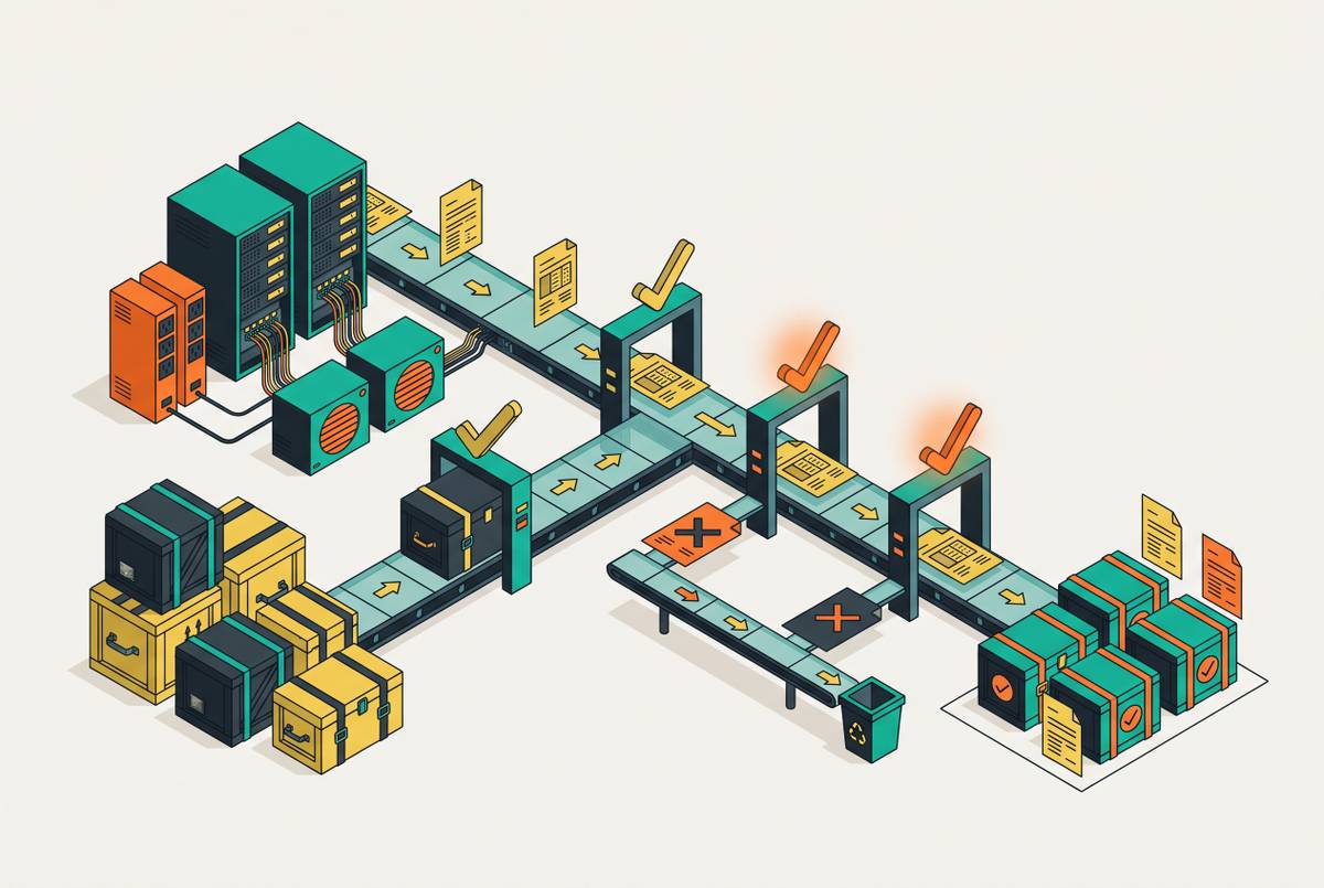
Cooling Zone Validation Rules for High-Density Data Hall Layouts
Designers must validate cooling zones separately because hall-wide metrics hide local overheating.
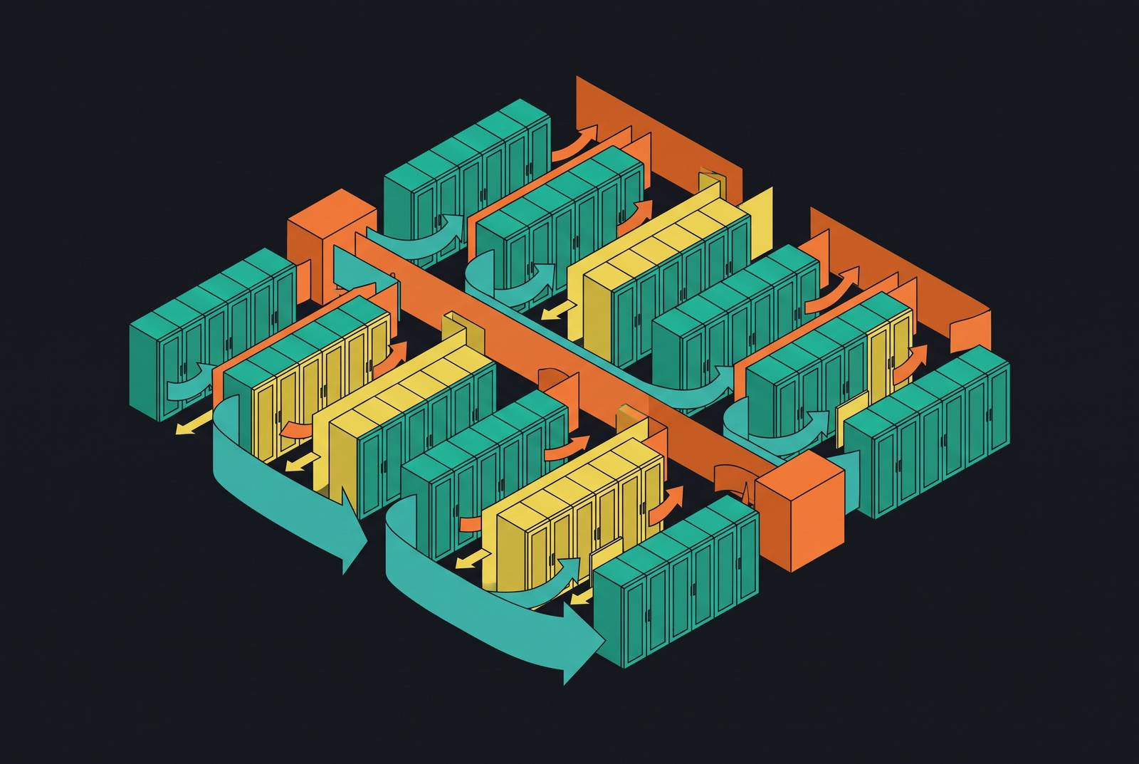
Rack density has gone from around 7 kW in 2021 to roughly 27 kW in 2026, and AI training racks now routinely blow past 100 kW. That spread, an order of magnitude between the lightest load and the heaviest in the same hall, is why no single cooling metric can describe what's actually happening on the floor anymore.
Why mixed-density halls make hall-wide cooling metrics insufficient
Mixed density isn't coming. It's already the default layout in most new builds. A hall with standard air-cooled racks sitting next to high-density liquid-cooled pods can't be governed by one aggregate number, because the thermal conditions that keep one load type safe are physically incompatible with what the other needs at hall scale.
Look at the actual hardware driving this. An NVIDIA GB200 NVL72 rack pulls a nominal 132 kW with peaks near 192 kW, and a GB300 NVL72 runs 132 to 140 kW. Those numbers aren't just cooling inputs, they're what the busway has to be sized for, and they explain why zone design has to be built around the peak case, not some comfortable average. Average out a hall that contains both an 8 kW storage rack and a 140 kW GPU rack, and the resulting number describes nothing real.
Most new builds have responded by going hybrid: air cooling for standard compute, liquid cooling for the high-density zones. And per the 2026 planning sources, designers are now running piping infrastructure during construction even when the first tenants don't need liquid cooling yet, simply because retrofitting a hall after it's built costs far more than getting it right the first time.
This is where people trip up. A hall-wide PUE can look fine. A hall-wide average inlet temperature can sit comfortably inside spec. And at the same time, a single zone can be overheating. The aggregate hides the local failure. Averages are built to smooth over exactly the variance that mixed-density halls now produce as a matter of course, and that makes it a structural problem, not a data quality one.
What ASHRAE TC 9.9 and 90.4 specify at the zone level
Two standards do the real work here, and they split the job cleanly. ASHRAE 90.4 caps how much energy the mechanical and electrical systems can burn per unit of IT load. ASHRAE TC 9.9 specifies what thermal conditions the equipment actually has to receive. One governs the plant, the other governs the air hitting the rack.
90.4 kicks in where conditioned floor space exceeds 20 W per square foot and IT equipment loads exceed 10 kW, and both conditions have to be true at once; below that line, 90.1 takes over. The 2025 edition is the current published version, but the 2024 IECC actually requires the 2022 edition. Anyone calculating compliance limits needs to check which edition their jurisdiction adopted before doing the math, because the answer isn't the same everywhere.
Compliance itself rests on two calculated figures. The Mechanical Load Component, or MLC, is cooling overhead per unit of IT energy, and it shifts depending on ASHRAE climate zone and on whether the design ITE power tops 300 kW. The Electrical Loss Component, or ELC, tracks power lost through the distribution chain, and unlike MLC it doesn't change with climate. Since the 2019 edition, the only mechanical compliance path left is a full-year energy model, so annualized performance is the standard now, not a design snapshot. Addendum g, approved in January 2024 and folded into the 2025 edition, split MLC into three segments, process cooling, process ventilation, and process heating, and partial renovations only need to hit the limit for whichever segment got touched.
TC 9.9 handles the equipment side through inlet temperature classes. A1 through A4 air-cooled gear has a recommended range of 18 to 27°C, with allowable ranges stretching from 15 to 32°C for A1 up to a wide 5 to 45°C for A4. In September 2024, TC 9.9 also put out a Technical Bulletin on liquid cooling resilience, laying out design strategies and failure mitigation because liquid cooling has become standard practice for AI-driven workloads rather than a niche approach.
A layout that lets H1 equipment receive supply air from an adjacent standard zone, even for a moment, even only under a failure condition, is non-compliant. Not suboptimal. Non-compliant, by the letter of the TC 9.9 inlet spec.
How cooling zones are physically defined
A cooling zone isn't a label on a floor plan. It's a physically bounded region where one coherent cooling strategy can hold consistent inlet conditions for every rack inside it, and the boundary is wherever that thermal contract stops being enforceable.
The 2026 planning literature generally splits zones into three tiers. Standard density is air-cooled, typically up to 10 to 15 kW per rack. High-density covers rear-door heat exchangers or direct-to-chip cooling, running 20 to 120 kW per rack. Ultra-high-density means immersion, 100 kW and up. Each tier needs its own cooling strategy and its own validation criteria; there's no shared rulebook across them.
Break the strategies down by practical density limit, and the constraints get specific fast. Standard air on a raised floor handles 5 to 15 kW per rack, and the thing that breaks it is airflow bypass and hot spots. Contained air, hot aisle or cold aisle, stretches to 15 to 25 kW, limited by high-velocity air management and fan energy. Rear-door heat exchangers reach 20 to 80 kW, constrained by how well the secondary water loop integrates into the hall. Direct-to-chip liquid cooling covers 50 to 120 kW and up, where coolant chemistry and internal plumbing become the limiting factor. Immersion cooling goes from 100 to 200 kW and beyond, but demands specialized chassis and maintenance procedures that most operations teams aren't set up for yet.
Where you draw the line between zones matters as much as which strategy you pick. The boundary has to sit wherever the thermal regime actually changes, not wherever a row of racks happens to end or a lease line happens to fall. A boundary drawn at a rack row that doesn't line up with an actual containment wall isn't a boundary. Rather than a boundary, it functions only as a suggestion.
Containment is how that boundary gets built for air-cooled zones. Cold aisle containment seals off the supply side, forcing air through the equipment instead of around it, and it delivers a real cut in cooling energy. Hot aisle containment seals the exhaust side instead, ducting hot air straight back to the cooling units, and it's documented to save up to 43% more than cold aisle containment, which is part of why it's become the preferred choice in new builds. Either way, blanking panels aren't optional. Every open rack unit is a bypass path, and a bypass path degrades the zone's thermal integrity whether anyone notices right away or not.
Airflow volume is the input that gets skipped most often. That volume has to be confirmed as physically achievable inside the zone before rack placement gets finalized, not discovered after the racks are bolted down. A rule of thumb from the Obelinf source calls for 100–160 CFM per kilowatt of IT load as an airflow quantity zone input, so a 10 kW rack requires a proportionally large volume of air delivered to its front, and this quantity must be confirmed as achievable within the zone before rack placement is finalized.
The specific validation rules that govern each zone type
Cooling zone validation rules aren't guidelines. They're pass or fail checks against numerical thresholds pulled straight from TC 9.9 equipment classes, 90.4's MLC limits, and basic containment physics, and a zone either clears them or the layout changes.
Inlet temperature rules split by zone type. In high-density zones housing H1 equipment, the band tightens to 18 to 22°C at every inlet, a four-degree margin instead of nine, and this is usually the first constraint to fail when a zone boundary starts leaking. An adjacency rule governs both: H1 equipment can't receive supply air that has mixed with return air from a lower-class zone, and the physical separation enforcing that rule is a checkpoint, not a nice-to-have.
Some rules cut across zone types entirely. Containment integrity is one: every open rack unit in a contained zone needs a blanking panel, full stop, and it's a pass or fail at the zone level. Every cable penetration through a containment wall has to be sealed, because an unsealed penetration is a bypass path that quietly degrades the zone's inlet guarantee. Boundary walls themselves need to run continuous from floor to ceiling, or to the underside of a contained plenum, and gaps at cable trays or raised-floor cutouts count as failures, not minor deviations.
Liquid-to-air heat rejection ratio is another cross-cutting check, specific to hybrid zones. Take a liquid-cooled rack drawing 132 to 140 kW, like a GB300 NVL72: roughly 90% of that heat goes into the liquid loop, and the rest goes to air. That residual air load has to be validated against the zone's actual air cooling capacity, not waved off as negligible. It's the coupling mechanism between liquid-cooled and air-cooled zones sharing a hall: if the liquid-cooled zone doesn't absorb its own residual air load, that heat becomes a contaminant next door. The validation rule follows directly: the air-side rejection capacity of a liquid-cooled zone has to handle the residual load of every rack in it at peak draw, not at some nameplate average that assumes everything runs quietly.
Capacity headroom gets its own cross-cutting rule too. Zone-level headroom, the gap between current IT load and the zone's cooling design capacity, has to be tracked separately from headroom at the hall level, because a hall showing plenty of room can still contain one zone already sitting at its limit. Partial PUE, or pPUE, measured per zone is what surfaces this in practice: it pinpoints which specific zone or system is driving losses, and a zone-level pPUE that's climbing is an early signal that headroom is eroding before anyone notices on paper. The rule of thumb: no zone gets planned to its full cooling design capacity without an explicit reserve built in, because the reserve is a validation input, not something to add later if there's room.
Last cross-cutting rule, and probably the least intuitive: EPMS-to-BMS signal validation. The Uptime Institute's Annual Outage Analysis found power was the primary cause of impactful outages for most operators surveyed, with cooling as a secondary cause. That coupling means the electrical power management system's state has to be visible to zone-level cooling controls. The rule: each zone's cooling logic needs confirmed signal paths from the EPMS covering that zone's power distribution. A zone whose cooling can't respond to a power state change in its own PDUs hasn't been validated, no matter how good its inlet temperatures look on a quiet day. For standard air-cooled zones housing A1–A4 equipment, validation must confirm that supply air temperature at every rack inlet falls within the TC 9.9 recommended range of 18–27°C under design load conditions, not just at the CRAH discharge point.
The failure modes that zone-by-zone checking catches and hall-wide metrics miss
Start with the most basic mismatch: a hall-wide average inlet temperature can be comfortably inside TC 9.9's recommended range while a single high-density zone runs hotter than 22°C at its worst rack. The average is answering a different question than the one that matters. It's just answering a different question than the one that matters.
Cross-zone thermal contamination follows a predictable path. The residual air load from liquid-cooled racks, roughly 10% of rack draw in current high-density setups, recirculates straight into adjacent air-cooled zones if the containment boundary between them isn't sealed. This isn't some edge case that only occurs under unusual conditions. It's the direct, foreseeable result of putting liquid-cooled and air-cooled zones in the same hall without enforcing physical separation at every single penetration. And the failure doesn't announce itself. Inlet temperatures creep up gradually in the neighboring zone, fans spin faster to compensate, and the zone loses margin well before any alarm threshold trips.
Containment bypass works the same way, just slower. One missing blanking panel, one unsealed cable cutout, one gap at an overhead tray, none of these cause an outage by themselves. Each one just shaves a little off the zone's thermal margin. Under normal load, the zone might still clear every inlet temperature check without issue. Push it to peak load, or take out part of the cooling plant, and all those small accumulated bypass paths add up fast enough to shove the zone past its H1 inlet limit. Zone-level validation catches this because it checks containment integrity as its own discrete pass or fail before any load gets applied. Hall-wide metrics have no mechanism to surface it at all.
Capacity headroom masking plays out at the planning level rather than the physical one. A hall can show comfortable aggregate headroom on paper while one specific zone is already operating right at its cooling design limit. That's what happens when headroom only gets tracked at hall scale. Add a new high-density pod to a zone that's already maxed out, and a hall-wide capacity plan will wave it through without ever flagging the problem, because the plan was never built to see zones individually in the first place.
The EPMS decoupling failure is the quietest of the bunch. A zone whose cooling control lacks confirmed EPMS signal paths can't respond when its own power distribution takes a partial hit, so the cooling plant just keeps running at whatever settings it had before the fault, while IT load shifts or drops underneath it. Depending on which way the fault goes, that produces overcooling or undercooling, and either one wastes energy or risks equipment. Worse, this kind of failure stays invisible operationally until a second fault lands on top of the first. Zone-level EPMS-to-BMS validation is the only check built to catch it before it turns into something that matters.
Why building information modeling software does not natively encode zone validation rules
Building information modeling handles geometry, clash detection, and equipment schedules well. It was never built to encode a rule like "H1 equipment cannot receive supply air mixed with return air from a lower-class zone," because that rule is not a geometric relationship but a thermal and operational one that depends on airflow behavior a 3D model doesn't simulate on its own.
That gap appears at handoff. The geometry can be complete and the validation can still be missing, because the model was never asked the question in the first place.
None of these are modeling failures.
Sources
- ASHRAE 90.4 Data Center Cooling Design: 2026 Compliance Guide
- Choosing the Right Cooling Architecture for Data Halls
- Data Center Cooling Best Practices: Airflow, Containment, and Density | Obelinf
- Data Center Energy Optimization 2026 Action Plan: A Practical Roadmap for Efficiency, Cooling, and Carbon
- CFD Analysis of Data Center Hall Cooling Performance under Normal and Failure Modes with Control Strategies and Airflow Leakages - Journal of Engineering Research and Sciences (JENRS)
- 1 © 2025 Dustin W. Demetriou The ASHRAE Thermal Guidelines for Data Centers
- Facilities Design for High‑density Data Centers IT@Intel White Paper Intel IT
- Higher Loads, Faster Builds: 6 Data Center Trends in 2026