BIM Level of Development Requirements for Data Center Equipment
Geometric accuracy alone won't capture the operational data that data center coordination demands.
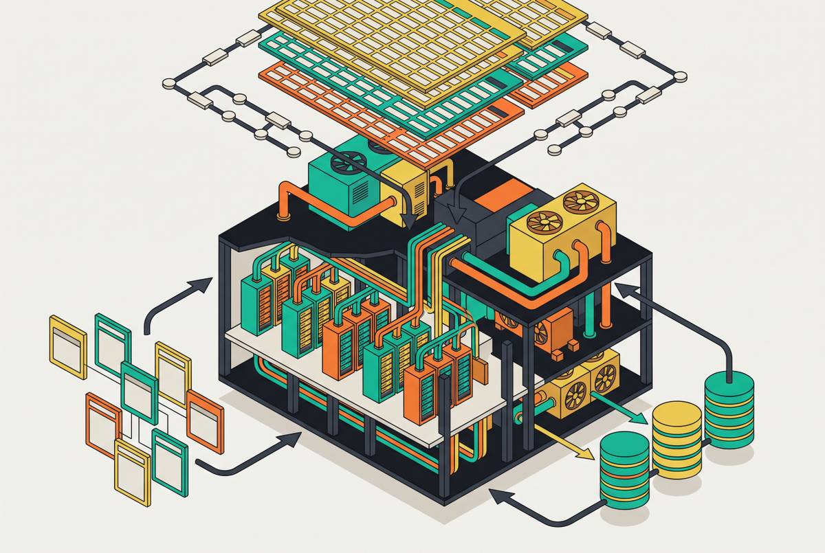
Data center equipment doesn't fit the BIM Level of Development ladder the way a wall assembly or a steel beam does. The LOD 100-500 framework was built for conventional building elements, and it still works fine for those. But racks, UPS systems, PDUs, cooling units, and cable trays carry operational data that geometry alone can't express, and the standard specification never quite catches up to that fact. This matters more every year, because rack densities keep climbing and every equipment decision now cascades into power, cooling, and structural consequences that a model without the right information simply can't flag.
What the LOD framework establishes: definitions, governing documents, and what each level authorizes
Two documents run the show in US practice, and they do different jobs. AIA Contract Document E201-2022, the BIM Exhibit, defines LOD 100 through 500 in contract language. That's the legal backbone. The BIMForum LOD Specification (current edition 2025, published by BIMForum USA) takes those bare definitions and applies them to hundreds of specific building elements, organized by CSI Uniformat 2010. BIMForum also added LOD 350, a level the AIA document doesn't include, because trade coordination needed something between "accurate geometry" and "ready to fabricate." Worth noting: BIMForum USA, which grew out of AGC and is now an independent nonprofit, is the only body licensed to publish or revise this spec. BIMForum Global is a separate outfit and has no authority over it.
Two terms get mixed up constantly, and the mix-up causes real problems on data center jobs. Level of Detail is about how much visual or geometric complexity an element has. It's an input. Level of Development is about how completely and reliably that element has been resolved and how much a downstream team can trust it. It's an authorized output. A rack family with slick rendering and rough dimensions is not LOD 300 just because it looks finished. LOD 300 means the size and location are accurate enough to build coordination decisions on top of.
LOD also applies element by element, not to the whole model at once. A single coordination model might carry structural steel at LOD 350, cooling equipment at LOD 300, and architectural finishes at LOD 200, all in the same file. That's normal, and it's exactly why data center teams need to specify LOD per system rather than picking one number for the whole project.
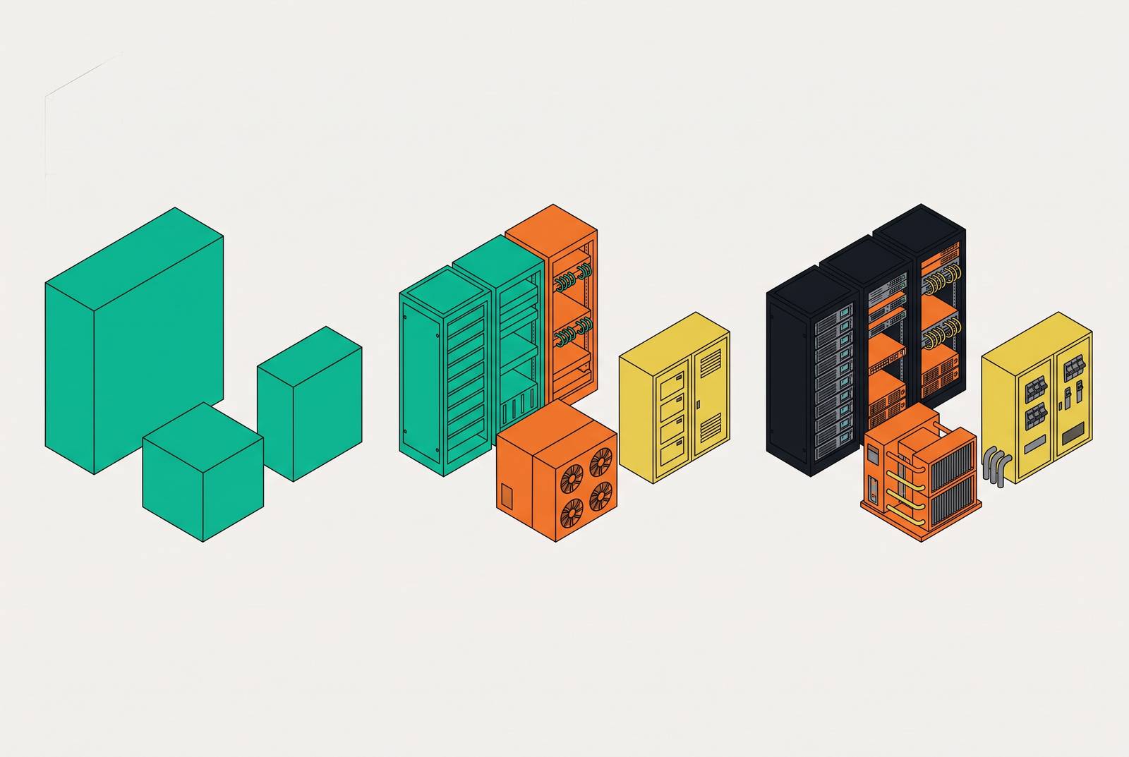
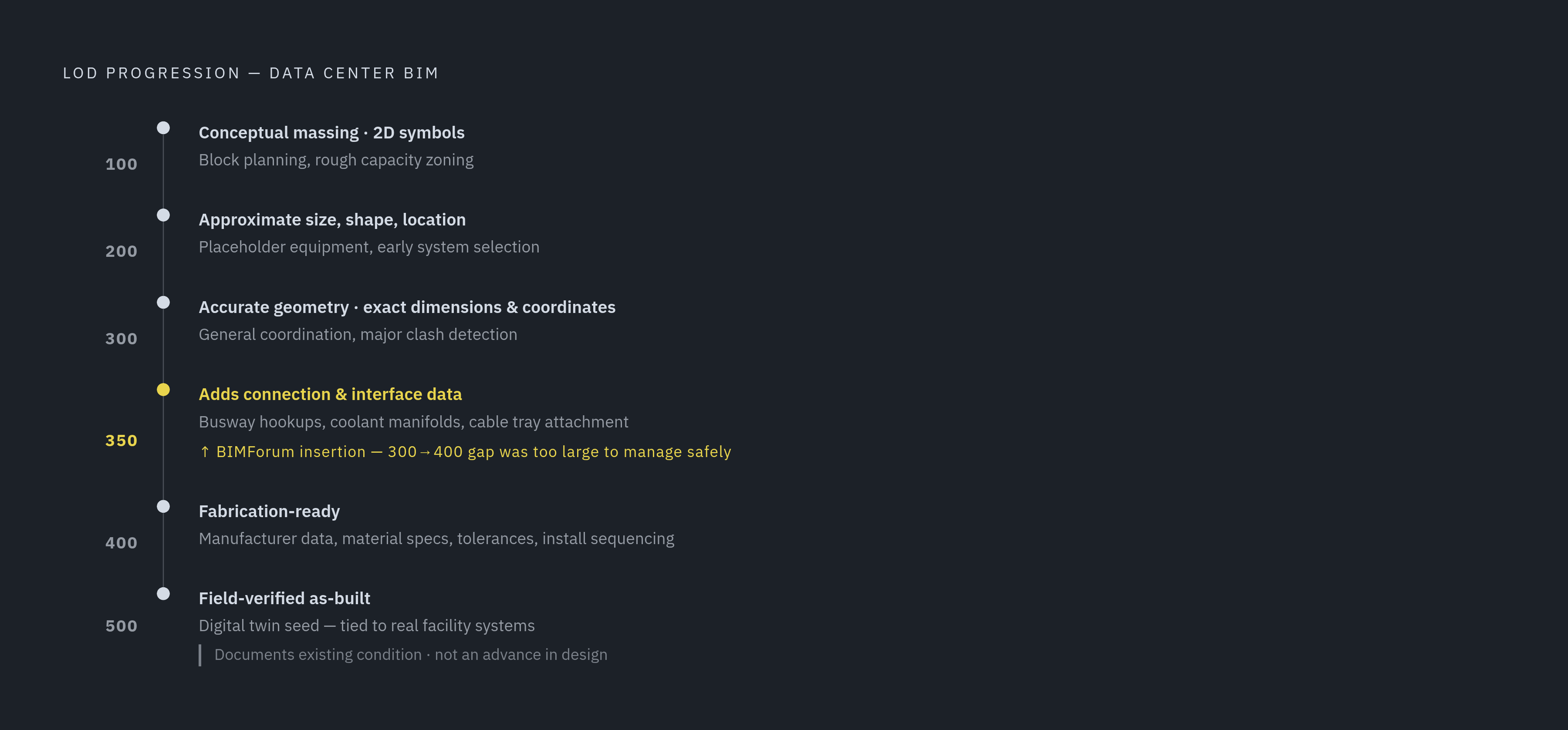
Levels 100 through 400 are minimums, and they build on each other. LOD 500 serves a different purpose by documenting field-verified as-built condition rather than advancing design geometry. Here's what each level actually authorizes, with the data center use case attached:
LOD 100: conceptual massing, 2D symbols. Good for data hall block planning and rough capacity zoning. No equipment geometry you can trust. LOD 200: approximate size, shape, location, orientation. Placeholder equipment for early system selection. Treat anything pulled from it as preliminary. LOD 300: accurate geometry, exact dimensions, exact coordinates. General coordination and major clash detection live here, though reliable clearance checking usually needs LOD 350. LOD 350: adds connection and interface data. Busway hookups, coolant manifold interfaces, cable tray attachment points, all become modeled information instead of guesses. LOD 400: fabrication-ready. Manufacturer data, material specs, tolerances, installation sequencing. This is the level prefab and shop drawings require. LOD 500: field-verified as-built. The starting point for a digital twin tied to real facility systems, where an ops team can pull maintenance history and live status off the model.
That's the ladder as written. It's coherent, and it's been tested on plenty of conventional buildings. Data centers are where it starts to strain.
Where the LOD ladder fits data center equipment
At the geometry level, the ladder actually maps onto data center delivery pretty well. LOD 200 for early layout, LOD 300 for spatial coordination, LOD 350 for trade coordination, LOD 400 for prefab. Teams are already running MEP-FP models to LOD 400 and beyond on fast-track schedules, feeding shop drawings straight out of the model. So the geometry progression works. It's just not the whole story.
The trouble starts with Uniformat 2010, the classification system BIMForum builds its element tables on. IT rack systems, liquid cooling distribution units, and battery energy storage are among the equipment types that don't map cleanly onto Uniformat's conventional building categories. The spec was built around conventional building elements, so its coverage of data center-specific equipment is limited.
That gap appears in a handful of specific places. Rated load, nameplate kW, A/B power path assignment, cooling method: none of that is geometric. A rack can be modeled at perfect LOD 300 accuracy and still carry zero information about whether it's rated for 8 kW or 80. Redundancy is the same problem in a different shape. A 2N power distribution setup needs two fully independent paths, physically separated and verified not to cross. LOD says nothing about whether that separation is even represented in the model, let alone checked.
Maintenance clearance is its own trap. A cable tray can sit in a geometrically perfect spot and still block the pull clearance on a UPS battery drawer or the swing radius on a PDU breaker panel. That's a soft clash, and no LOD number catches it automatically. It has to be modeled as an explicit clearance volume and called out in the BIM Execution Plan, or it just doesn't get checked.
Asset identity runs into the same wall. The tag, the serial number scheme, the DCIM asset ID, the cost code, none of that lives inside an LOD definition. It's a separate layer of information that has to be specified on purpose, or it evaporates somewhere between design and handoff. Liquid cooling makes things worse still: cold plate manifolds, coolant distribution unit piping, and leak detection cable routing have no established LOD interpretation under the current Uniformat-based spec.
Some frameworks handle this by splitting the concept in two: geometric LOD on one side, Level of Information (LOI) on the other, covering specs, cost codes, maintenance schedules. That split matters for operations, where a facility manager might need dense information on a piece of equipment whose geometry is dead simple. Internationally, the field is moving toward Level of Information Need (LOIN) under ISO 7817-1:2024, which lays out how to define the geometric detail, the attributes and the documentation needed across a built asset's life cycle. Whatever term a project uses, it needs to be nailed down in the BIM Execution Plan early, or different teams end up assuming different things about the same deliverable.
Telling a modeler "LOD 300 for the UPS system" tells them how accurate the box needs to be. It says nothing about the operational data the facility team needs the day they take over the building. That has to be specified separately, system by system.
LOD requirements mapped to specific data center equipment categories
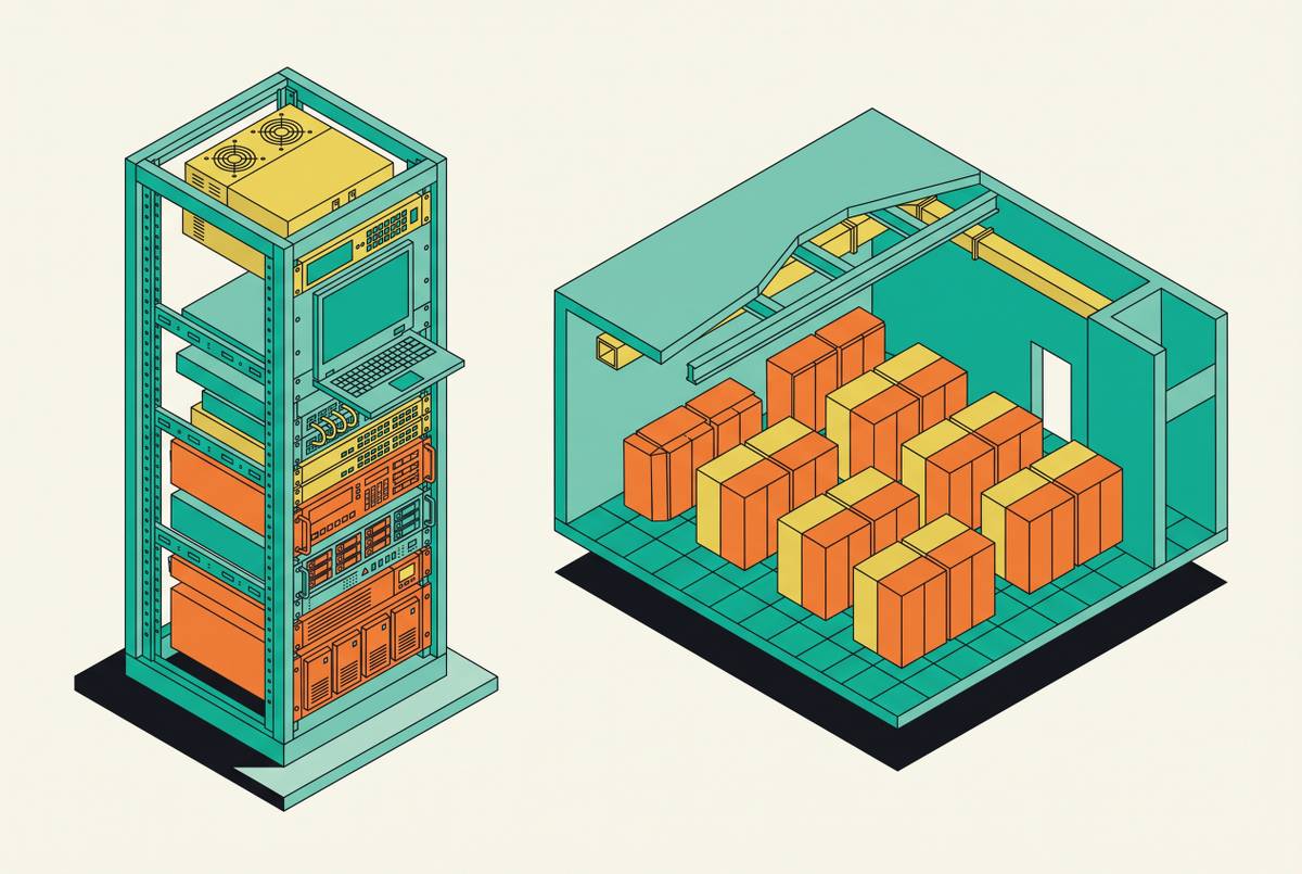
IT rack systems and containment. At LOD 200, a placeholder footprint is enough for data hall layout and aisle orientation. LOD 300 needs accurate height, width, depth, precise location, and containment geometry, because MEP routing can't be coordinated against racks until then. LOD 350 adds connection and interface data relevant to trade coordination, such as power connection points and attachment locations. None of that touches the parameter that actually drives the project: rated load per rack. Rack densities that sat around 30 to 40 kW a few years back are now landing in the hundreds of kilowatts for AI workloads, according to Google distinguished engineer Sakalkar's remarks at Data Center World. That rated load field in the rack family isn't decoration. It sizes the power and cooling systems behind it.
UPS systems. LOD 300 covers accurate geometry and location, and battery cabinet arrangements shift a lot depending on topology. LOD 350 brings in connection and interface data, including service access zones that matter for maintenance clearance. Prefabricated UPS modules push to LOD 400, where fabrication-ready detail covers manufacturer-specific dimensions, tolerances, and installation sequencing. None of that geometry reveals the kVA rating, the topology, or which path, A or B, a unit sits on. A one-line diagram won't catch a redundancy violation. The model has to be detailed enough to prove the two paths never physically touch.
PDUs and power distribution. LOD 300 gets the accurate geometry and exact location of the distribution equipment. LOD 350 adds connection and interface data, including power entry and distribution points. The branch circuit schedule, breaker ratings, circuit assignments, load balancing, all of that needs a live link back to the model rather than a spreadsheet that drifts out of sync. Color-coding A and B paths directly in the model is a common way to catch accidental overlap before it becomes a construction problem.
Cooling: CRAC, CRAH, chilled water, and liquid cooling. LOD 200 is fine for early capacity zoning. LOD 300 nails down equipment dimensions and connection points. LOD 350 adds piping flanges, drain pans, condensate routing, underfloor plenum tie-ins for raised-floor CRAC units. Liquid cooling breaks the mold entirely: cold plate connections at the rack, secondary loop interfaces, coolant distribution unit manifolds, leak detection routing, none of it has a real home in the current spec. Air cooling faces practical density limits before physics gets in the way. Direct-to-chip cold plates now handle the higher densities that AI deployments demand, with immersion cooling taking over at the very top end. That makes liquid cooling coordination the normal case for new high-density halls, not a special exception someone deals with later.
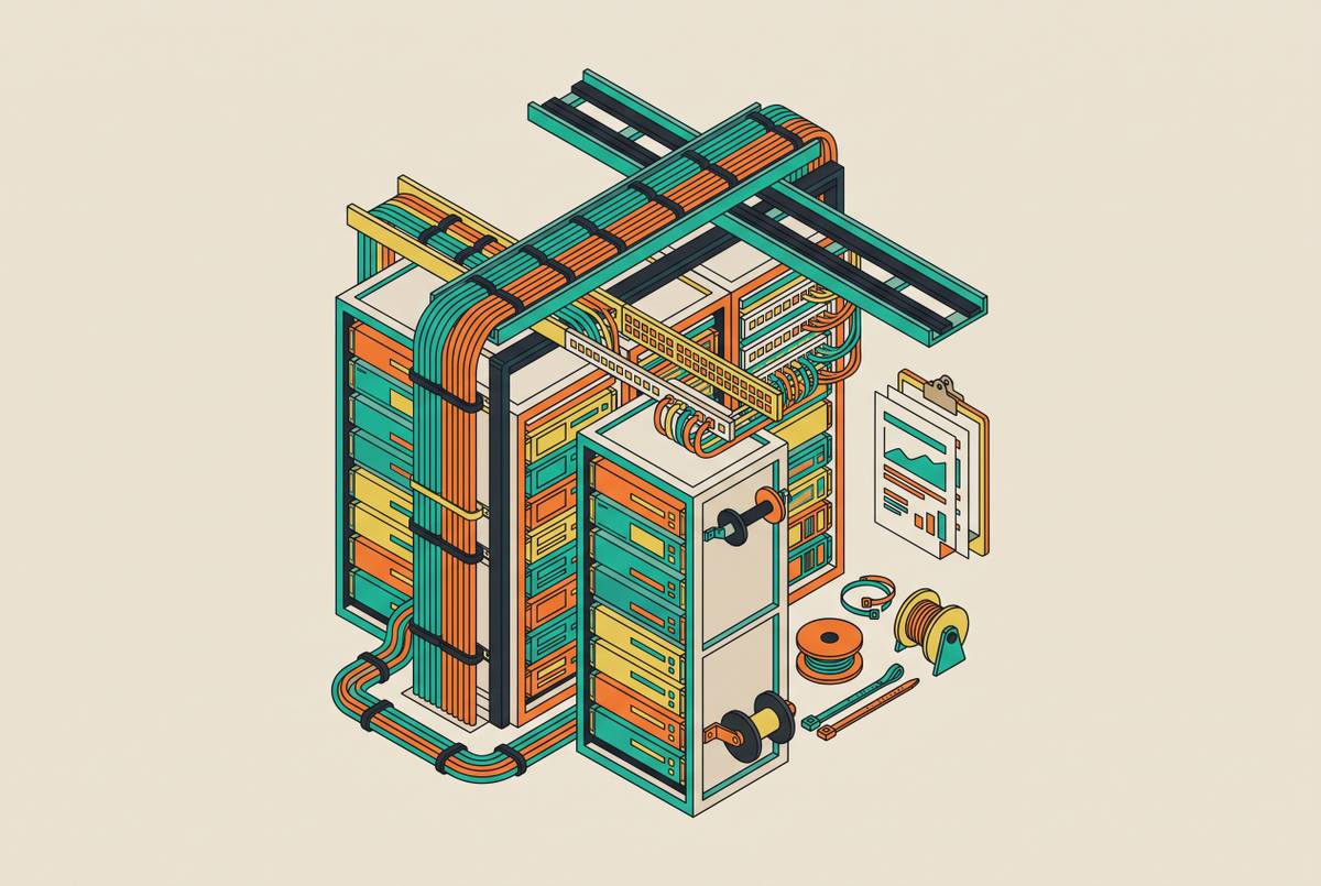
Cable trays, conduit, and underfloor infrastructure. LOD 350 is really the floor for reliable coordination in the crowded overhead and underfloor zones. Connections, supports, hanger points all need to be in the model before an install sequence means anything. Overhead in a data hall usually stacks cable trays next to chilled water piping, busways, lighting, and fire protection, so the soft clash clearance around any maintenance access point has to be modeled on purpose. Underfloor, the raised floor cutouts and cabling pathways need to be checked against structural supports, and that check only holds up at a sufficiently high level of geometric accuracy. Cable fill ratios, pathway zoning between power and data, future capacity headroom, all of that lives in the information layer, not the geometry.
Generators and BESS. Generators need LOD 300 for footprint, exhaust routing, fuel connections, and acoustic enclosure geometry, with LOD 350 adding transfer switch connections and load sequencing. CMiC reports that more data centers now include battery energy storage systems, and bringing BESS in late can push the critical path back by months. BESS also drags in structural loading, fire safety zoning, and electrical sequencing that touch the base building, none of which the standard element interpretations account for. The fix is the same every time: get the LOD and information requirements written into the BIM Execution Plan before the system gets added, not after.
What LOD 350 and LOD 400 require for data center prefabrication and trade coordination
BIMForum added LOD 350 for one specific reason: the jump from LOD 300 to LOD 400 was too big to manage safely on the trade coordination floor. In data centers, that middle ground is where the expensive conflicts either get caught or get missed. Busway-to-rack connections, coolant manifold interfaces, cable tray attachment points, equipment support structures, all of it needs to be verifiable in the model before crews show up with the actual hardware.
Soft clashes are the real risk in that zone. Two components can sit a foot apart, never intersect, and still violate a required maintenance clearance or a code minimum. A technician who can't reach a valve or pull a breaker panel because a conduit run sits four inches too close isn't a modeling failure anyone will catch with standard clash detection; it's a failure that only shows up if someone modeled the clearance volume on purpose and checked it. That's the real value LOD 350 adds on a data center job: not just cleaner geometry, but a place in the process where connections and access get resolved before fabrication locks them in.
LOD 400 finishes the job for anything getting built off-site. Manufacturer-specific dimensions, tolerances, anchorage details, cable entry points, and installation sequencing all need to be present, because a fabrication shop can't work off approximate numbers. Given how fast rack densities and cooling requirements are moving, that fabrication-ready model is doing more than describing a part. It's carrying the load, cooling, and power path decisions that will define how the facility actually runs.
Sources
- BIM Level of Development (LOD) 100, 200, 300, 350, 400, 500
- Level of Development (LOD) Specification – BIM Forum
- BIM for Data Center Construction: Smarter Project Delivery
- BIM as a Solution for Complex Data Center Projects
- What Is Level of Development (LOD) in BIM? A Complete Guide | AIA Contract Documents
- Levels of Development (LOD) in BIM | Autodesk
- modmation.com
- teslaoutsourcingservices.com