Hot-Aisle Containment Design Coordination With IT Layout
Coordinating rack layout, cables, and cooling prevents field rework and containment failures.
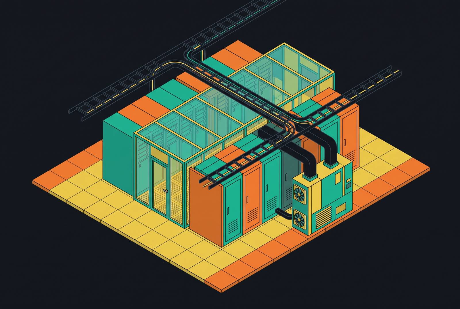
Hot-aisle containment design coordination with IT layout is about keeping one physical enclosure intact across several teams’ decisions. Rack positions, cooling returns, cable routes, and structural clearances must be designed together, because a change in one constrains the others. That coordination must also reach operations, or routine equipment moves will undo the separation the design established.
Why HAC design cannot be resolved discipline by discipline
A rack position fixes part of the containment boundary, which constrains the panels, which in turn constrain cable openings and overhead routes. Those routes must also leave room for the cooling infrastructure that takes in the exhaust. A decision that works for one discipline can therefore make another discipline’s design unworkable. By the time someone specifies the containment panels, earlier decisions may already limit their ability to form a continuous enclosure. Treating HAC as a cooling add-on puts coordination after the choices it needs to shape.
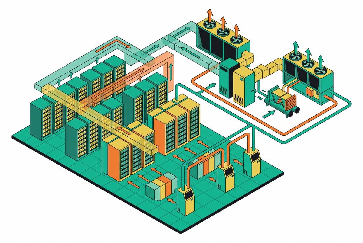
Servers face the cold aisle and draw room air, while doors, roof panels, and walls enclose their hot exhaust and direct it back to the CRAC/CRAH return. That separation must hold at every rack, cable opening, and access door. TRG Data Centers identifies rack alignment, gap sealing, roof panel continuity, cable management, and door-seal integrity as recurring failure points. Each involves more than one of the teams that lay out equipment, route services, and design containment.
As a result, approval within each discipline does not establish that the combined design works. A rack repositioned for IT reasons can leave a gap in the row, while a network cable route can pierce a panel without a sealing detail. A cooling zone drawn without input from IT can leave high-density equipment outside the planned return path. These are not simply defects in a containment product. They are unresolved dependencies that cause field questions or rework.
How rack layout decisions set the constraints that containment must then satisfy
Rack layout is the first major constraint because it determines the shape that containment must seal, the load it must serve, and the access it must preserve. Yet IT teams usually fix that layout before MEP coordination starts. This sequence leaves the mechanical and electrical disciplines working around positions they did not help establish. The arrangement must leave the other systems a workable design.
Back-to-back alignment establishes the hot aisle, while front-to-front alignment establishes the cold aisle. A single rack outside that arrangement can create a bypass path through which exhaust returns to the cold side. The containment boundary therefore follows more than the general outline of a row. It depends on the position of each rack within it. TRG Data Centers flags inconsistent alignment across rows and racks displaced during equipment changes or maintenance as common oversights.
Density zoning adds a thermal constraint to that geometry. Grouping high-density racks together concentrates the heat that the cooling return must receive, so a sealed enclosure alone does not resolve the design. Its return capacity must match the load from within the zone. DOE's Best Practices Guide addresses IT environmental conditions before the requirements they set for mechanical and electrical systems. That sequence reflects the dependency between equipment placement and the systems serving it.
Unsealed equipment bays let hot air pool and flow back to the cold side, even where the row itself is aligned. TRG Data Centers identifies these spaces as a source of hidden hotspots and recommends blanking panels. Their absence is therefore a layout and sealing failure. When equipment changes alter those spaces or move a rack, they reopen a design decision that may have been treated as final.
Cable routing as a structural input to containment, not an afterthought
Once the rack layout sets the shape of the enclosure, cable routing sets where services must pass through it. A cable path through the rear of a rack or a panel opening can create a bypass unless the opening is sealed. Cable pathways and panel layouts therefore need to be resolved in the same design session. Designing the boundary first and the penetrations later leaves its integrity dependent on later corrections.
The conflict is not limited to holes in panels. Bundles that block rear rack doors or hang into the hot aisle reduce the effective cross-section available for exhaust to return to the CRAC/CRAH units. TRG Data Centers identifies cables obstructing rear-rack airflow and unsecured cables hanging into containment as a distinct failure category. Its mitigation uses trays and ties arranged to keep cables clear of vents and rear doors. Those trays need a route that reaches the equipment and is compatible with the airflow path.
Underfloor pathways compete with cooling airflow for plenum space and make uniform cold-aisle temperatures harder to maintain. Overhead pathways in the hot-aisle zone must fit around the roof panels and keep their seal intact. DOE's Best Practices Guide treats cable management as a key part of making air management work and covers it just before aisle separation and containment. It does not state that one is a formal precondition for the other.
Power redundancy adds more routing volume to this shared geometry. Architectures such as 2N and N+1 add more cables across each row, more penetrations that need seals, and more crowding above the enclosure. Those requirements cannot be separated from the space reserved for roof structure and mechanical distribution. Cable routing is therefore another set of constraints propagated from the IT layout.
The overhead zone where cooling infrastructure and cable trays compete for the same space
Above the contained hot aisle, these dependencies converge in a single crowded zone. Roof panels, server-row cable trays, chilled water supply and return mains, and fire suppression branches all need space there. The roof must attach at the top of the racks and form a continuous horizontal seal. An overhead element that interrupts that plane requires either a coordinated penetration detail or a routing revision. This is where simultaneous coordination stops being a general principle and becomes a question of what can physically fit.
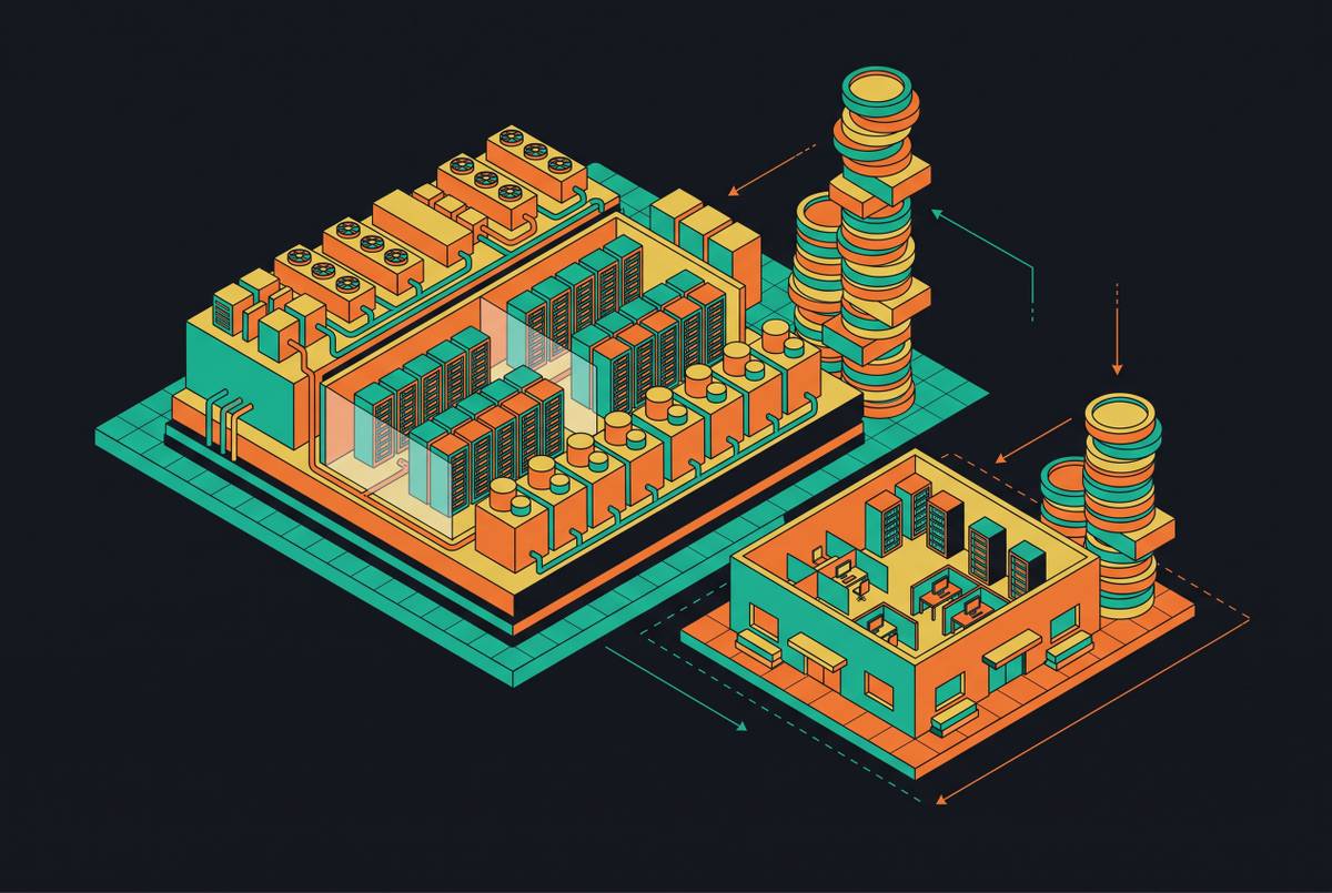
A cable tray and a chilled water main still clash if they need the same clearance, even when each route works on its own drawing. Resolving that clash in the field typically produces a change order of $15,000–$40,000, plus schedule impact. Moving one route also changes its relationship to the containment roof and the other services around it. After a route is changed, the enclosure must still seal.
HAC brings additional coordination work because enclosing the hot aisle at the ceiling also involves fire suppression, lighting, and cable and power penetrations. Cold-aisle containment that leaves the ceiling open does not impose that burden to the same degree. Roof continuity is part of HAC performance. Structural clearances and service routes must permit that continuity. Otherwise, the enclosure is compromised by the infrastructure it was expected to accommodate.
Retrofits make the spatial conflict sharper. Higher-density layouts can require new overhead infrastructure, including coolant distribution lines for liquid-cooled racks, in a zone already occupied by legacy cable trays and existing MEP. The containment roof then has to seal around both the old and the new infrastructure. CFD analysis can reveal recirculation patterns that the physical layout alone does not predict, with plenum depth, ceiling height, and tile placement among the variables studied. But airflow analysis does not remove the need to resolve competing routes and their penetrations in the available space.
How HAC performance degrades when maintenance and equipment moves break the coordination that design established
A rack addition, maintenance opening, or equipment move alters a boundary that several systems rely on. The facility may still have its original cooling equipment and containment components, yet no longer have the separation those components formed at commissioning. Performance can drift without a wholesale redesign. The change is often in how the parts meet.
That degradation is incremental. A door remains ajar after maintenance, a roof panel removed for access is not replaced, or a repositioned rack leaves an unsealed gap in the row. Each opening may look minor when viewed as the residue of a single task. Together, they make it harder for the enclosure to keep supply air and exhaust apart. TRG Data Centers identifies moved equipment, unresolved temporary openings, and incomplete barriers or seals after time-pressured maintenance as a distinct HAC failure category.
Other failures preserve the visible enclosure while disrupting the airflow logic within it. Poorly ventilated PDUs can contribute to heat buildup in the hot aisle. Their position relative to containment barriers is set during design, but whether their ventilation remains adequate is an operational monitoring responsibility. Perforated tiles create another dependency between layout and airflow. Tiles moved into the hot aisle during equipment work let supply air into the exhaust return path.
TRG Data Centers identifies improperly placed perforated tiles as an airflow-path failure and places them only in cold aisles. Temperature data alone may not immediately localize a displaced tile after equipment work. Operations therefore needs more than a temperature reading to understand why the layout is no longer performing as intended. It needs to know how the layout works: which openings let supply air in and which boundaries keep exhaust separate. Without that knowledge, maintenance can get the equipment working again while leaving gaps in how the systems fit together.
What the handoff to operations must carry for containment design intent to survive commissioning
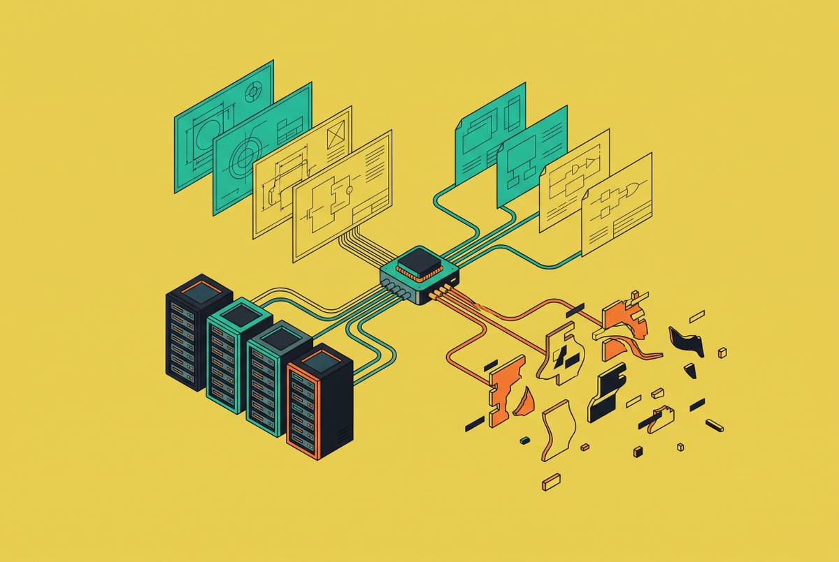
Preserving that arrangement requires a handoff that carries the design decisions along with drawings of the finished installation. Rack layout, cable routing, cooling zones, and overhead clearances must be captured in structured data that DCIM, BMS, and facility teams can use. A PDF set and a model that cannot be queried do not make those relationships operationally usable. Teams need to retrieve what a change affects and why.
The first task is schema alignment. Teams must agree on the information each system needs and can accept. Only some BIM attributes matter to operations, and BIM can fill only some DCIM fields. The delivery contract must therefore define what gets captured, its format, its delivery milestone, and who is responsible. Progressive acceptance gates make that information a deliverable before turnover. DCIM must also be provisioned before construction is complete so as-built conditions can be captured incrementally, before contractors demobilize and the window for accurate capture closes.
For HAC, the handoff must preserve cooling zone boundaries and their relationship to rack density assumptions. It must carry containment panel locations and sealing details at every cable and power penetration. Sensor positions and temperature thresholds must describe acceptable containment performance. The tile layout must show which tiles are perforated and which are solid, and why each goes where it does.
When rack layout, cable routes, cooling zones, and containment geometry share one coordinated model, a rack change can propagate through the affected systems. ArchiLabs Studio connects layouts, critical-systems engineering, cable routing, documentation, and operations-ready handoff inside a single workflow. That approach turns a cascade that costs hours of manual rework across power, cooling, cable, and sheets into a managed, traceable update.
The handoff is therefore part of containment design. Coordination survives only when its rules and relationships become part of how the facility manages change.