Cooling Load Coordination Between IT Layout and Mechanical Design
Connected workflow lets IT and mechanical design respond to each other before construction starts.
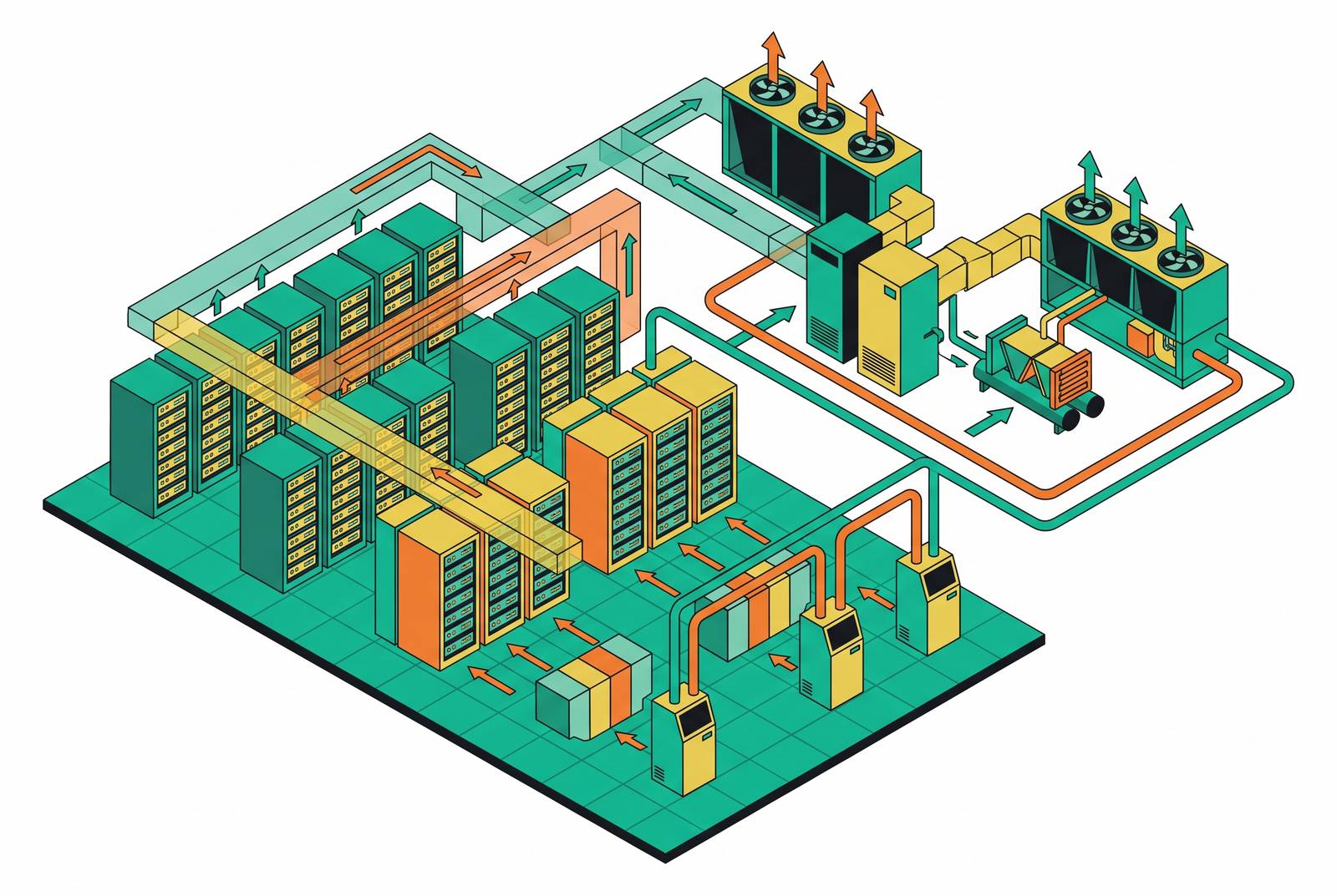
Cooling load coordination between IT layout and mechanical design is about keeping the heat map and the cooling system in step. Every rack placement is also a cooling decision. When those decisions travel through separate tools and document handoffs, the gap becomes a physical constraint. A connected workflow closes that gap while the design can still change, rather than leaving construction and operations to absorb it.
Why rack placement is a mechanical design decision, not just a spatial one
Heat from a rack has to go somewhere, immediately. Placing that rack fixes the location, magnitude, and concentration of a heat source that the mechanical system must remove continuously. Data centers run at sustained thermal loads with no overnight setback, so this is fault-tolerant heat removal. As density rises, the thermal mass that once gave operators a buffer disappears. A high-density hall can move from normal to critical in well under a minute after a cooling failure.
That makes the position of the load as important as its size. Cooling capacity alone cannot resolve a mismatch between where heat lands and where airflow or liquid circuits can carry it away. Which way racks face, how rows are laid out, and where cooling routes run are all parts of the same physical design. Yet the teams that choose rack locations and the teams that design heat removal often make their decisions separately.
How the disciplines responsible for layout and cooling end up working in isolation
IT and network planners place racks around connectivity, zone adjacency, and phasing. Mechanical engineers often start with a static watt-per-square-foot assumption for the room, leaving individual heat sources unmapped. Both teams can work carefully with the information they have and still make designs that do not fit together. The missing link is a shared data model that exposes the thermal consequence of a layout move. Without it, that consequence can remain invisible until the design is committed.
The split also separates the energy compliance model from the physical thermal model. A spreadsheet can show that an energy calculation passes while return air recirculates and leaves the top third of every rack running hot. The calculation has not necessarily captured where the heat is or how it moves through the room. As a result, passing the calculation and delivering the intended room performance become separate achievements. Neither one, by itself, proves the other.
BIM raises the ceiling for coordination, but a building model does not natively carry every relationship this work needs. Rack-level power chains, cooling circuit assignments, and airflow zones must be available if mechanical engineers are to respond to rack moves in real time. Without those relationships in the model, teams still have to translate data for one another. That fragmentation follows from contracts, tool licensing, and information handed over as documents rather than live, queryable data. It is a workflow problem.
What ASHRAE 90.4 actually requires, and why a siloed design process struggles to satisfy it
ANSI/ASHRAE Standard 90.4 calls for two numbers to be calculated, the Mechanical Load Component and the Electrical Loss Component, and each must be checked against its own limit. The current edition was published October 2025. The mechanical compliance path that remains calls for an energy model of the full year based on the actual design. The Mechanical Load Component, or MLC, accounts for energy used for cooling, fans, pumps, and heat rejection against IT equipment design power. Economizer-friendly climates get roughly half the allowance of tropical climates, so free cooling becomes part of the plan to meet the limits as well as a way to save energy.
Addendum g, approved January 2024 and carried into the 2025 edition, split the MLC into process cooling, process ventilation, and process heating, with heat recovery subtracted. Partial renovations need to meet the limits only for the segments being modified. The Electrical Loss Component, or ELC, covers losses in the UPS and ITE distribution segments. From the 2025 edition, the calculation of UPS efficiency must use all the capacity available, including redundant online modules. The incoming electrical service segment was removed because federal transformer and feeder rules already cover it, so older calculation templates can misstate the required assessment.
These requirements make a disconnected design process harder to defend. A late layout change can shift heat distribution and invalidate the airflow model behind the mechanical calculation even if the reported number still passes. California's 2025 Building Energy Efficiency Standards, effective January 1, 2026, add a prescriptive requirement that must also be reconciled during design. Each cooling system that mainly serves a computer room with a power density greater than 20 W/ft² must have an air or water economizer that can carry the full expected cooling load under the specified favorable outdoor conditions, with exceptions for smaller loads. A static assumption for the whole room cannot, on its own, show how that requirement applies to the loads each system serves.
How rising rack density has sharpened the cost of getting coordination wrong
Higher density turns the coordination gap from an efficiency concern into an architecture problem. Requests for design loads above 100–200 kW per rack are growing more common, which forces changes to the mechanical and electrical design of whole halls. Once loads cross what air cooling can serve, placing equipment also commits the project toward a cooling method. Liquid cooling is now a mainstream consideration in most new projects, but choosing it does not settle the design. It still has to fit power, monitoring, and operational systems.
Jadhav et al.'s life-cycle co-design study places cooling at 33 to 40% of total data center energy use for typical air and water-cooled facilities. The study uses the Frontier supercomputer at Oak Ridge National Laboratory to ground the problem at exascale. With a peak power demand of 30 MW, Frontier needs liquid infrastructure to carry away its heat at all times. At that scale, cooling plant topology is not a detail to settle after rack planning. The number of subloops and the assignment of coolant distribution units shape the plant that must carry the load.
Redundancy changes that topology decision too. The same study finds that the subloop count that minimizes cost and carbon without redundancy is not the right answer once N+1 standby capacity is priced. Redundancy policy therefore has to precede commitment to the mechanical layout. Simply overprovisioning power and cooling for AI-scale density is capital intensive to the point of impracticality.
Where coordination failures surface during construction and commissioning
If a rack row is added, a zone is repurposed for higher density, or a hot aisle shifts, the thermal load map changes. In a siloed workflow, airflow zones, cooling unit positions, and pipe routes may remain tied to the previous layout. The drawings then describe a thermal arrangement the finished room will not match. Resolving that mismatch can require cooling unit repositioning and pipe rerouting while construction is already underway.
The overhead plane makes the conflict visible. Cable trays serving server rows compete with chilled water supply and return mains for the same space. When those routes are designed separately, the field team inherits a collision between systems that both need a continuous path. Resolving it consumes space and time that coordinated design could have preserved. The result can be field clashes, commissioning delays, and limits on usable capacity.
Commissioning cannot erase every constraint established before equipment arrived. Once concrete is placed and systems are installed, correction becomes harder, and deficiencies discovered in service may require downtime or phased shutdowns. Where correction is not practical, the facility may have to accept limits on capacity, efficiency, or expansion. Missing routes and fixed spatial conflicts persist despite overtime as predictable consequences of uncoordinated changes.
How the handoff to operations inherits whatever coordination was skipped in design
Turnover does not close a gap that the design data still contains. The BMS controls and monitors the mechanical and environmental plant, while the EPMS monitors the electrical path from utility to rack. DCIM keeps track of IT assets, rack space, power capacity, and network connectivity in the white space. It consumes data from the other systems, which retain their roles. Operations therefore depends on each system working and on the relationships between these systems.
Those relationships need a structured handoff. BIM models do not natively contain all the rack-level power chains, cooling circuit assignments, and fiber panel schedules that DCIM requires. Without those structures, someone still has to translate data by hand from the construction model to the live operations platform. If layout and cooling were never iterated together, the rack registry delivered to DCIM may not match the thermal zones managed by the BMS. Operators then receive records of different designs for what is supposed to be one facility.
That mismatch follows the facility into its next change. Every rack move or capacity addition can require manual rework across power, cooling, cable, and documentation. Operators must also work out what caused thermal incidents from records whose links were never fully matched up. Structured design data carried through turnover is what prevents that repeated reconstruction. Otherwise, the same fragmentation that slowed design becomes a recurring operating burden, and the facility falls short of its own design intent.
What a connected workflow looks like when cooling load follows rack placement in real time
In a connected workflow, placing a rack changes the thermal load in a shared, live data model. Rack wattage, airflow class, cooling type, and redundancy requirement sit in the same structured environment as the mechanical relationships they affect. Moving a rack updates the cooling model without a separate document handoff. Constraints then become visible in the updated cooling model while the layout is being shaped, before another team has accepted a snapshot. Cooling load follows placement because the relationship is part of the model.
Subloop count, coolant distribution unit assignment, and pipe routing can be evaluated before construction fixes them in place. ASHRAE 90.4 compliance becomes a live check against the evolving design, including at the final gate. As the layout changes, the MLC calculation can reflect the current mechanical design and flag when it falls outside its compliant limits. The value is not merely a faster calculation, but a calculation tied to the room being designed.
Deterministic rule engines provide defensible checks for regulatory submissions and AHJ review. AI-assisted layout generation can accelerate iteration, but human verification remains necessary before compliance is claimed. ArchiLabs Studio applies the connected-workflow principle across layout, critical-systems engineering, cable routing, documentation, and operations-ready handoff. It connects tools through a single, always-in-sync source of truth, so a rack move cascades through power, cooling, cable, and sheets, automating the separate manual revisions.
The same structure supports turnover. Rack power chains, cooling circuit assignments, and thermal zone boundaries can populate operational systems from model data, eliminating re-entry from PDFs. That carries the coordinated design into DCIM, EPMS, and BMS without discarding the relationships established during design.
The design decisions that are hardest to recover once coordination is deferred
The hardest decisions to recover are those that become the plant's physical structure. In Jadhav et al.'s life-cycle co-design framework, subloop count and coolant distribution unit assignment are decisions that become fixed when the plant is built. Its optimum configuration saves $63k against the documented as-built configuration of three duty subloops. Yet the framework is explicitly a greenfield design tool because converting a built plant does not pay back.
Liquid cooling has the same timing problem because it locks in choices about the structure, piping, and controls. Support for direct-to-chip and rack-level liquid systems must precede rack layout. Floor and ceiling decisions are similarly durable. Slab flatness affects rack alignment, while structural penetrations and hanger spacing fix the space available to cable trays and chilled water mains. A missed relationship can become a permanent spatial constraint.
Operational data is less visible, but it also becomes harder to recover when deferred. Relationships never captured during design must be reconstructed manually from commissioning observations, leaving an incomplete basis for later changes. Treating coordination as a late review therefore accepts more than rework risk. It accepts that some decisions will be locked in wrong and that operations will have to live within them. Deferring cooling load coordination is not just a scheduling choice, but a facilities outcome that can last for the entire service life.