BIM Limitations for Data Center Critical-Systems Coordination
BIM's clash detection misses the logical and sequencing failures that break data center redundancy.
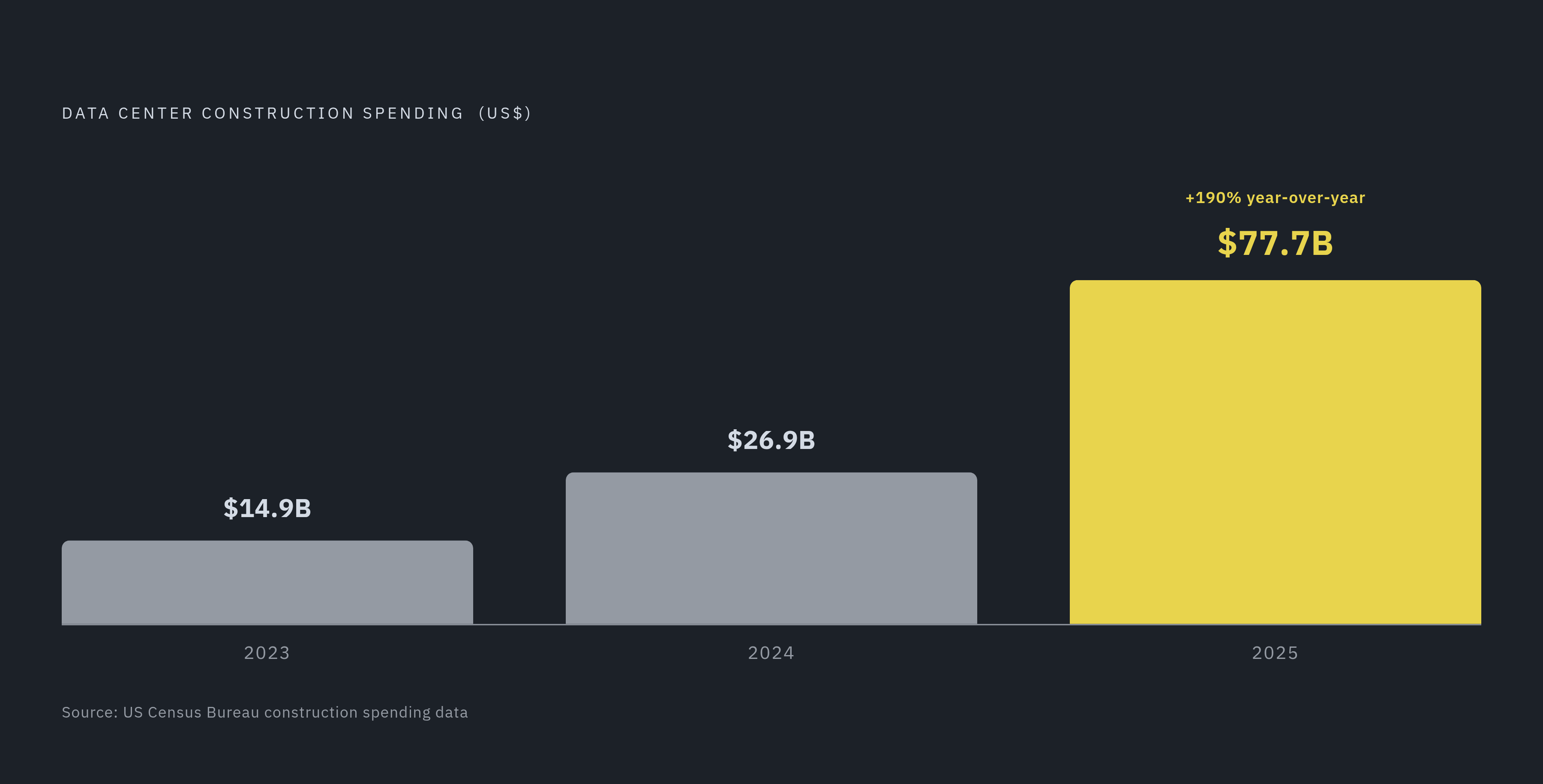
Data center construction spending in a major market jumped from $14.9 billion in 2023 to $26.9 billion in 2024, then to $77.7 billion in 2025. That's a 190% year-over-year jump. Growth that fast doesn't just mean more buildings going up. It means more coordination errors happening faster, at a scale where a mistake that used to cost a rounding error now costs a line item someone has to explain to a board. BIM is the tool the industry leans on to catch those mistakes before they hit the field, and it was built to solve a problem data centers only partly have.
What BIM was designed to solve and where that design assumption breaks down
BIM's real contribution to construction was getting rid of stacks of separate 2D drawings and replacing them with one federated 3D model, where you can actually see if a duct and a beam are fighting for the same six inches of space. For most buildings, that coordination problem is the whole problem. Office towers, hospitals, schools: the dominant question is geometric. Do two things collide? BIM answers that well, and it changed the industry for the better.
Data centers ask a second question that geometry can't answer. Positioning matters less than the logical relationships between things. Power path A has to stay separated from power path B all the way through the building, or the redundancy the whole design depends on falls apart. Cable tray fill ratios have to stay under NEC limits. Airflow return paths have to stay clear. Redundancy schemes have to hold up as genuinely independent systems, not just independent-looking geometry.
Clash detection software scans a federated model fast and flags where objects overlap. A clean clash report feels like a green light. It isn't one. The software can't tell you whether a valve is actually reachable once the equipment around it goes in, or whether a service corridor that clears the minimum width on paper is something a technician can actually work in with a cart and a toolbox. Sequencing conflicts slip through entirely: one trade runs pipe behind conduit another trade already hung, and nothing in the model ever flags it, because nothing collided.
And the model doesn't know what N+1 means. That logic lives in the engineer's head and in a spec document somewhere, not in the geometry. This finding does not knock BIM. It's just a description of what geometry-first coordination was built to catch, and where its job ends.
How MEP density and redundancy architecture expose the geometry gap in practice
Hyperscale facilities pack hundreds of interdependent MEP systems into the same ceiling spaces and service corridors. Push one federated model to hold all of that, and performance drops off fast: clash detection slows down, navigating the model gets clumsy, and coordination meetings turn into scrolling exercises. The fix, according to The AEC Associates in a May 2026 analysis, is splitting the project into infrastructure-based zones: pod-based coordination for white space, system-segregated models for electrical rooms, separate packages for underfloor services, discipline-specific linked models for utility areas. One giant model can't carry that much complexity. It was built for something else.
The underfloor void is its own problem, and most teams still treat it like an afterthought. Standard BIM workflows are built around ceiling coordination, because that's where most building trades fight for space. In a data center, the raised floor carries power cabling, network cabling, chilled water piping, grounding systems, and airflow all at once. Treat that space as leftover routing room and you get installation failures and airflow failures the model never saw coming, because nobody built the model to look there in the first place.
A-side and B-side power separation is the same story from a different angle. Standard electrical coordination doesn't enforce separation between redundant pathways. Shared routing or overlapping access zones can quietly undercut the resilience the whole design was supposed to guarantee, and no clash detection run will ever catch it, because nothing physically collided.
Vendor equipment models make this worse in a smaller, more irritating way. Manufacturer files often ship with bad connection points, extra geometry nobody needs, and metadata that doesn't match anything else in the project. Drop them straight into a live coordination model and the whole thing gets unstable, with hidden clashes buried in the noise. The fix is swapping them out for simplified coordination-level families instead: accurate dimensions, real maintenance clearances, verified connection points, the service zones actually required.
Phasing adds another layer. Big data center projects deliver white space in stages, often long after the core infrastructure goes in. Try to manage every future phase inside one live model and confusion sets in fast. The model's structure has to separate the phases. The schedule alone won't do it.
Prefabrication, now standard on hyperscale builds, raises the bar again. It needs LOD 400: exact component specs, hanger locations, access zones, connection points, all modeled before anything gets cut or welded. Per Resolve's July 2026 analysis, errors caught after fabrication cost rework, return trips, and schedule damage that never should have happened. Confirming LOD 400 in the proposal stage, not after the contract's signed, is the lesson that keeps getting learned the hard way, project after project.
Rework runs around 30% of total cost on complex construction projects, with data centers sitting at the high end of that range. A 2025 study in the Journal of Construction in Developing Countries analyzed 65 MEP clashes on a single project and found those conflicts drove additional costs of MYR 60,323.80. That's what one coordination gap looks like once it compounds through a whole build.
Cable routing and fiber: the coordination discipline BIM models treat as an afterthought
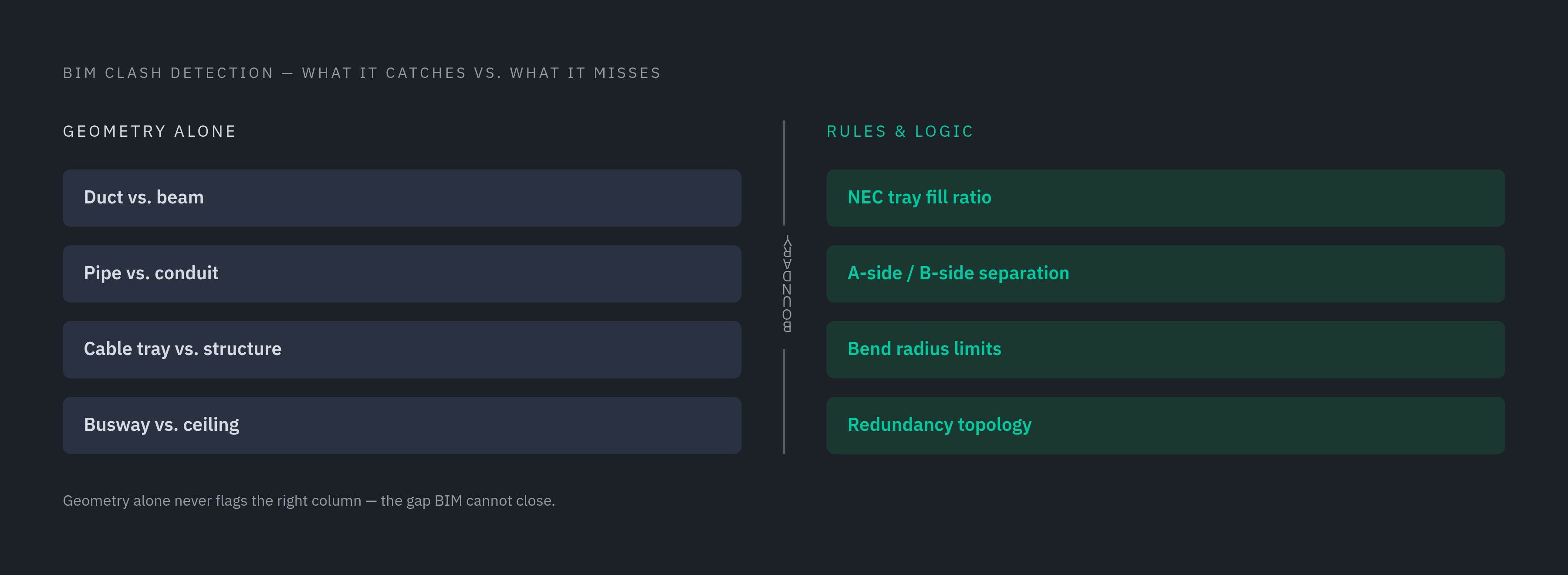
Data centers route thousands of cables across multiple levels at once. Raised floors carry heavy power feeds, ceilings hold fiber trays, risers connect systems floor to floor. Stack all of that into shared corridors and the congestion has nothing to do with clashing geometry. It comes from rules the model doesn't know exist.
Those rules compound fast. Power and communications cabling need vertical separation from each other. Path A and Path B power cabling has to sit in separate trays, a redundancy requirement, not a nice-to-have. Fiber has strict bend radius limits a geometry model won't enforce on its own. NEC fill ratios cap how much cable a given tray size can carry, and the model doesn't calculate that either.
Multiply those constraints across the rack count in a hyperscale hall and you get hundreds of feet of tray that all has to coordinate with busway above the racks, lighting, pre-action sprinkler piping, and return air ductwork. The coordination surface is enormous, and rules govern it, not shapes.
The standards keep moving, too. Industry standards bodies are actively working through cabling standardization for hyperscale GPU clusters, with connector and interface specifications still evolving as speeds scale toward 800G and beyond. HVDC power distribution adds another wrinkle: as that architecture spreads, the separation requirements for cable trays need rethinking to account for the different characteristics DC distribution introduces.
Poor cable pathway planning can choke off airflow in hot aisle configurations, so the cable problem and the thermal problem are really one problem wearing two hats. They interact in ways that only rule-based intelligence and structured data can catch, well beyond what a clash check between two geometric objects will ever flag. Cable tray routing in a data center is its own discipline, with its own rule book, and plain BIM geometry doesn't enforce any of it on its own.
Liquid cooling and rising rack density are making the thermal coordination problem worse
AI workloads are pushing rack density from conventional levels toward significantly higher per-rack power draws. Facilities designed around yesterday's average density face retrofits that cost real money once that demand shows up. The real constraint lies elsewhere, beyond the building envelope. It's the thermal and power envelope the room was actually built for.
Liquid cooling adds an entire second loop to the building. The technology coolant loop brings its own piping, stainless steel, chilled water connections, condensate drainage, and all of it needs the same modeling rigor the power side gets. CRAC unit placement, return air paths, condensate drainage: none of that should be assumed. It needs clearance and routing worked out ahead of time, not guessed at during install.
Raised floors and perimeter cooling, the traditional playbook, aren't enough anymore for serious AI workloads. Operators are shifting toward chilled water loops and structural systems built for heavier computing loads, and the physical shape of the building is changing faster than the coordination workflows built for the last generation of facilities.
CFD (Computational Fluid Dynamics) simulation is becoming close to standard practice as a supplement. Feeding BIM models into CFD lets teams study airflow across hot and cold aisles and check rack layouts before anything gets installed. But CFD sits outside BIM: a separate analytical layer that BIM feeds into rather than something BIM does on its own.
Hot and cold aisle containment adds yet another layer of 3D coordination: containment systems have to work alongside airflow, cable trays, lighting, and structural elements all at once. As covered in SMACNA's October 2025 article on BIM-driven solutions for data center projects, this gets treated as its own distinct BIM service area, not a side effect of routine MEP coordination. As density climbs, small miscalculations in airflow or power distribution push a system past its design limits fast. The model needs to carry thermal logic, not just thermal shape.
The handoff gap: what BIM delivers at turnover and what operations actually needs
BIM data reaching turnover is routinely incomplete, inconsistent, or just disconnected from how operations teams actually work. The model that did real work during design and construction doesn't automatically turn into the structured dataset operations needs on day two.
Some of that fragmentation goes back decades, and it's baked into where each system came from. BMS, SCADA, EPMS, and DCIM each arrived from different vendor ecosystems and different operational traditions. Each system arrived with its own vendor, its own contractor, its own console, its own buyer. The result is what amounts to swivel-chair operations, with a cooling alarm showing up in one window, the electrical event that caused it showing up in a second window, the affected tenant's cabinet showing up in a third, and a person sitting between all three trying to connect the dots by hand.
The systems split along real functional lines. BMS handles facility-level HVAC and environmental controls. EPMS handles electrical distribution and energy metering. DCIM ties IT and facility data together into one operational view, at least in theory.
Integration failures show up in specific, recognizable ways. The "two-master polling" problem happens when EPMS and BMS both query the same meter at once, throwing off communication errors and data conflicts. A firmware update or a hardware swap can quietly break data mappings, especially without a protocol integration register tracking every gateway, its configuration file version, its mapped data points, and who owns it.
Real handoff needs more structure than a model export. It needs a structured handover schema, an EPMS/BMS/DCIM integration plan, asset IDs, parameters, and location referencing built to support fast impact analysis whenever something changes. It needs BIM tied directly into BMS, EPMS, a maintenance management system, and DCIM. Not a PDF sitting in a folder somewhere, waiting for someone to reopen it during an outage.
Equipment data trapped inside manufacturer PDFs is intelligence that never reaches the operations team. Spec data that flows straight into models, schedules, and validation rules is the difference between a BIM model that serves construction and one that keeps serving the building after it opens. Capacity planning through a connected digital twin can track power and cooling metrics as density climbs, but only if the model carries structured data, not just shapes.
What fills the gap: connected automation across power, cooling, cable, and handoff
None of this argues for dropping BIM. It argues for connecting BIM's geometry to the rule-based intelligence and structured data needed to carry what geometry alone can't.
Treating BIM as the finish line is the mistake worth naming directly. It's the start line for a second layer of work that most teams never budget for, and that gap is exactly where the rework numbers above come from. Connected coordination workflows add a few things plain BIM doesn't do on its own. Deterministic rules check separation requirements, fill ratios, redundancy topology, and bend radius, checks a geometry-only clash run never makes at all. Cascading change logic means when a rack moves, the power path, the cooling loop, the cable tray routing, and the documentation all update together instead of needing manual rework across five disciplines. Structured asset data carries from design straight into DCIM, EPMS, and BMS as a live, queryable dataset, instead of geometry exported once at turnover and forgotten in a folder. Parametric automation handles layout generation and capacity planning, and Connected prefabrication and coordination workflows have been associated with 20–40% schedule compression and meaningful gains in space efficiency.
ArchiLabs' Studio Mode (archilabs.ai) is built around exactly this gap. Teams build out data hall options, place equipment, and route power, cooling, cable tray, and fiber using reusable automation recipes. The platform checks capacity, redundancy, separation, access, and route continuity, then generates sheets, schedules, reports, asset registers, and structured handoff data for Revit, AutoCAD, Excel, DCIM, EPMS, BMS, and whatever system the owner runs. It connects the coordination layer to the operational layer inside one workflow, instead of treating them as two separate jobs handled by two separate teams months apart.
AI and deterministic rules aren't interchangeable, and mixing them up is where a lot of these tools go wrong. AI is the right tool where flexibility and language matter: interpreting a formal information request, generating layout options, pulling spec data out of a manufacturer PDF. Deterministic rules are the right tool where precision and compliance aren't negotiable: NEC fill ratios, separation distances, redundancy path validation. Hand a rules job to AI, or a judgment call to a rigid rule set, and you end up with creative work that's too boxed in or safety checks that aren't strict enough. Neither failure is acceptable at hyperscale.
Prefabrication readiness is a decent test of how mature a workflow actually is. LOD 400 fabrication-ready models need exact component specs, hanger locations, access zones, and connection points modeled before anything gets cut, and connected workflows that carry structured data straight through into fabrication packages are the only realistic way to hit that bar at hyperscale pace. Teams running on connected data instead of manually re-entering information at every handoff report on-site time compression of 20 to 40% and material waste cut by 10 to 20%.
The BIM execution plan and the governance around it still matter as much as ever. The federated model needs clear ownership, LOD requirements written into contracts, and a protocol integration register covering the operational systems layer. Automation doesn't replace any of that work. It just gives the model somewhere useful to go once construction ends and the building starts running.