Parametric Data Hall Layout Generation for Capacity Planning
Parametric rules automate data hall layouts as density and cooling demands shift.
U.S. data center construction hit $48.18 billion in 2024, headed for $112 billion by 2030, and almost none of that growth comes from general IT expansion. AI compute is the driver, and it runs at densities that break the way data halls have always been built. The gap between conventional data hall assumptions and what a modern GPU cluster needs isn't a gradient anymore; it's a cliff that shows up the moment you try to scale.
Next-generation high-density racks throw out a conventional hall's assumptions about structure, power, and cooling all at once. Every layout decision made in the first weeks of design either keeps future capacity open or closes it off for good, and at hyperscale, closing it off carries costs that can be extraordinarily difficult to reverse.
What static layout workflows were built for, and where they break
CAD drawings and spreadsheets worked fine for a long time because rack density stayed fairly uniform, and cooling was one variable: how much air you could push through a room. A drafter set a layout once and touched it up by hand whenever something changed, because things rarely changed together. That held up as long as density stayed flat.
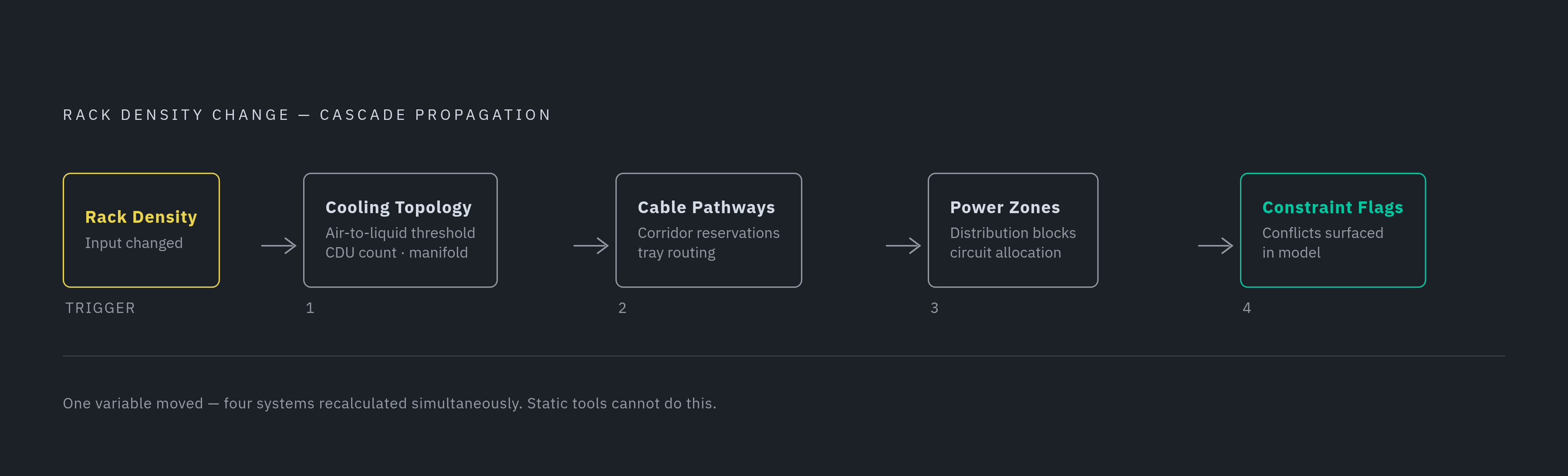
AI-era density breaks that game at the root. Push rack density up, and you force a cooling regime change. That repositions the CDUs and manifold corridors, which shoves cable pathways out of the way, which reshapes power distribution. Every parameter drags the others with it, and static tools can't carry that ripple through a design. Each trade redraws its own piece and hopes the others line up. They rarely do, and the mismatch usually shows up on-site, not on paper, which is the worst possible place to find out.
The pace makes this worse. Data center starts logged $14 billion in a single month in July 2025, and at that speed, manual back-and-forth between disciplines stops being an annoyance and turns into a wall. Power purchase agreements have grown to enormous scale, and grid capacity constraints have become a real planning factor in major markets. Treat power budget as an afterthought instead of a hard constraint at that scale, and the risk isn't theoretical: it's a rack row that gets built and can't be energized.
How parametric layout generation encodes capacity constraints as rules
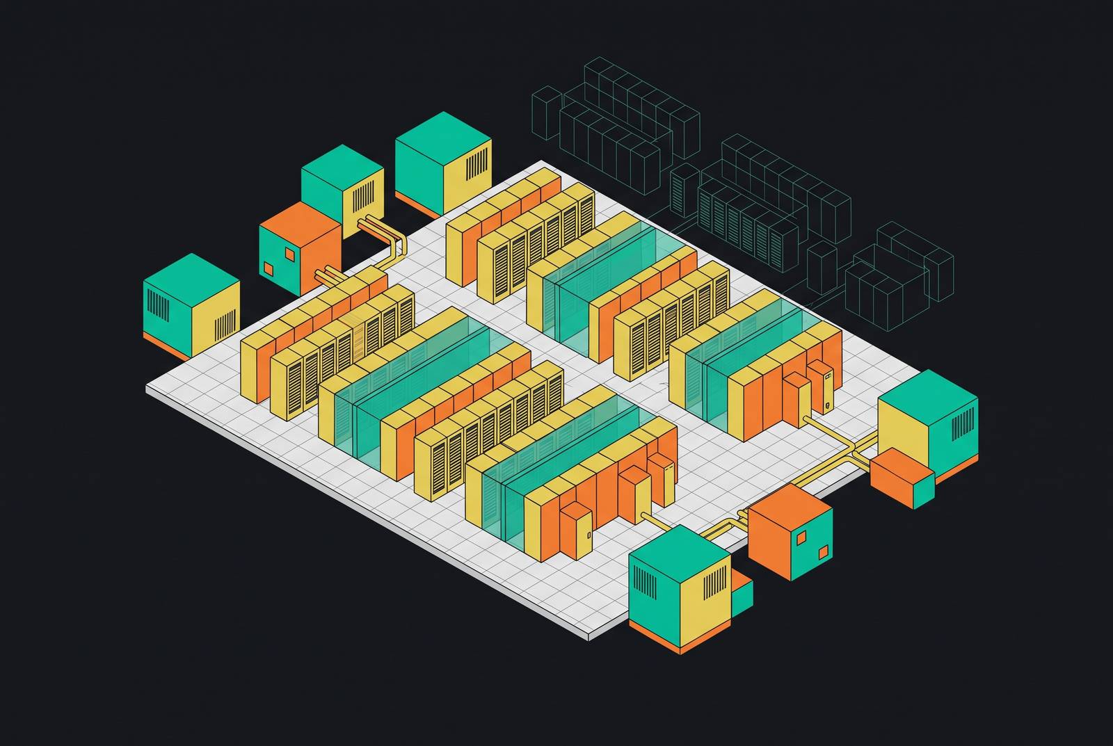
Parametric layout generation means the spatial design comes out of a rule set, not a drafter's hand, and the layout updates on its own the moment a rule changes. Any workflow that still depends on someone redrawing a hall by hand after a density change is already behind, and there's no polite way to say it: that team is going to get outpaced by whoever isn't doing that.
BIM, as most teams use it, gives you a 3D space where disciplines coordinate and check for clashes. Parametric generation adds the logic that decides what goes inside that container in the first place, and it recalculates the moment an input changes, without anyone touching a mouse.
What actually gets written into the rule set:
- Power budget per zone. Rack rows can't exceed a set kW ceiling without triggering a recalculation of the whole layout.
- Cooling regime thresholds. Cross from air into liquid, and the spatial grammar of the hall changes: CDU placement, manifold corridor widths, leak-containment zones, all of it.
- Aisle strategy. Hot-aisle and cold-aisle containment geometry comes out of the rules, not a habit a drafter picked up years ago.
- Floor load distribution. Rack weight and cooling unit weight decide where rows can go, worked out up front instead of checked after the fact.
- Cable tray fill limits. Tray capacity gets sized as a multiple of the initial cable volume, because future cabling always grows past the first estimate. That ratio is a rule, not a hunch.
None of this needs AI inference. These are precision constraints where a wrong answer has physical consequences: a rack that overheats, a floor that can't take the load, a tray that's full before phase two even starts. Deterministic rules belong here; save the probabilistic guessing for lower-stakes work. Change the rack density target from one regime to another, and the system recalculates cooling topology, moves the infrastructure corridors, and flags anything that breaks a constraint, all without anyone redrawing it by hand.
Liquid cooling as a spatial planning problem that parametric tools must solve first
Liquid cooling stopped being a niche choice once air ran out of room to work. Past a certain density threshold, fans and chilled air can't pull heat out fast enough. Industry projections put cold plate shipments and liquid-cooled capacity on a path to become the dominant cooling mode within a few years.
Treating liquid cooling as a drop-in swap for a CRAH unit is the mistake that costs the most later. It brings entirely new things into the room: coolant distribution units, manifold routing corridors, leak-containment zones, CDU screening clearances. All of that claims floor space and overhead space that used to belong to rack rows and cable trays.
Vendors don't agree on how any of this works, either. Coolants, connectors, flow rates, pressure limits, manifold geometry all vary supplier to supplier. A parametric system has to carry each vendor's specifics as its own constraint set. Treat them as interchangeable, and you end up with a manifold that doesn't fit the corridor built for it, discovered on the day it's supposed to be installed.
Liquid-cooled builds in the U.S. carry a meaningful cost premium over air-cooled construction, which makes getting the layout right early a line item, not a nice-to-have. Skip modeling liquid cooling as a first-class spatial element from the first layout pass, and retrofitting it into a hall built for air carries substantial costs on a mid-size project. Parametric generation flips the order most teams still use by default: CDU placement and manifold corridor width shape where the rack rows go, ahead of rack placement rather than after it. Get that order backwards and you're negotiating with pipes that were never going to fit.
Power topology and cable routing as layout-generating constraints, not downstream details
The cost of bad sequencing shows up repeatedly in practice. When mechanical, electrical, and plumbing trades get coordinated after the layout is already locked rather than while it is being built, conflicts that could have been caught early instead surface on-site, where fixing them is far more expensive. That sequencing mistake, not any single design error, is what costs the money.
Trades fight over the same overhead space constantly. Chilled water piping and CRAH units compete with electrical busways, and power cable trays block return air paths. Put an electrical run in the wrong spot, and you throw off pressure balance across the whole aisle. These are geometry problems, plain and simple, and parametric rules catch them before anything gets built.
Power architecture puts its own weight on the layout, too. The electrical train, meaning utility feeds, generators, ATS, switchgear, UPS, PDUs, needs a footprint reserved in the plan from day one, well before rack rows go down. Reported shortfalls in transformer and distribution unit supply mean sizing decisions made now lock in procurement timelines months or years out. Layout rules need to carry those lead times as constraints, not push them off as someone else's problem later. Even EPMS point lists and branch-circuit monitoring density push conduit routing volume up, one more claim on the space the layout has to reserve.
Cable and fiber routing belong in site design from the start, too. Installed tray capacity needs headroom well above the initial cable volume, and that ratio gets underestimated constantly when nobody writes it down as a rule. Power and fiber trays need minimum separation clearances, which roughly doubles the pathway space actually required. High-density interconnect technologies running through AI GPU clusters introduce their own spatial and routing demands that feed straight back into the layout's planning constraints per zone.
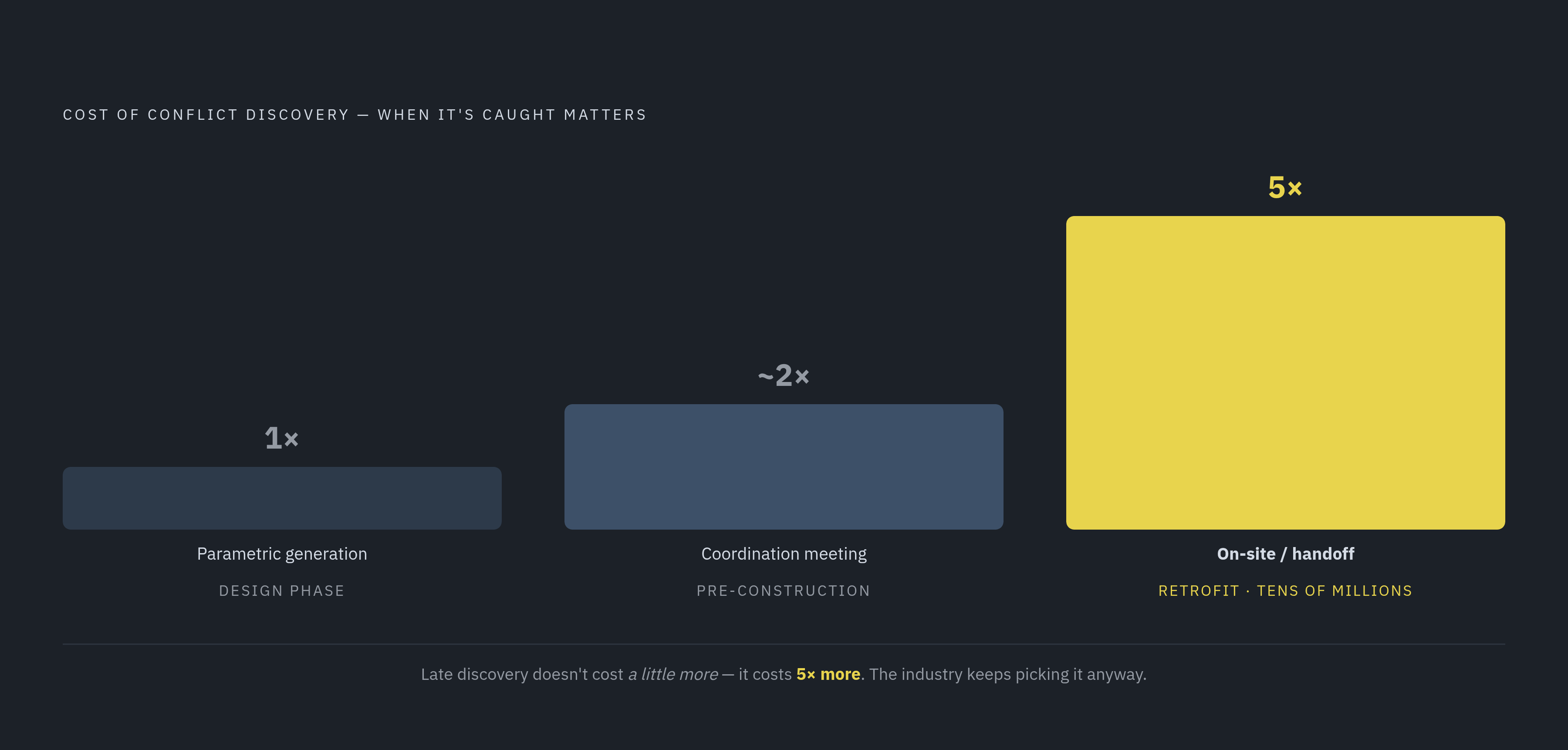
Put power topology, cooling topology, and cable routing into the same rule set, generating layout together instead of in sequence, and the output comes out already coordinated. Conflicts get caught at the source instead of discovered on-site, months later, at five times the cost.
Where BIM supports parametric layout and where it falls short without additional automation
BIM is close to mandatory on data center projects at scale now; building without it has become almost unthinkable. Higher BIM maturity means smarter models, more predictable workflows, and better ground for AI-assisted analysis down the line.
Still, BIM as most teams actually use it functions as a coordination and clash-detection platform, and that's a narrower job than people give it credit for. It's very good at telling you a wall and a duct occupy the same space, after someone's already drawn both. Generating geometry from a set of constraint rules in the first place sits outside what it does, since it can only check what's already there, never produce it, and that distinction matters for everything that follows.
The limits are documented, too. A 2025 arXiv study found LLM-based BIM information extraction tops out at an accuracy well below what you'd want for unsupervised use in a safety-critical workflow. That finding backs up the case for deterministic rules governing anything with physical consequences. Automated BIM pipelines also lose spatial accuracy on non-orthogonal geometry, which matters the moment you're dealing with curved halls or campus-scale layouts instead of a plain rectangular room.
MEP coordination failures usually trace back to the same root cause: each trade models its own systems independently, and the coordination model only finds where they collide, after the fact, without stopping the collision from happening. Parametric generation, with disciplines built together from the same rule set, prevents the clash instead of just flagging it after someone's already poured concrete around it. That's the gap BIM alone doesn't close: encoding capacity, cooling, and power constraints as rules that generate the layout. BIM is where those outputs live; the rule engine is what produces them.
What operations-ready handoff requires from a parametric layout from the start
Handoff problems are data problems, most of the time. If asset attributes, equipment tags, point lists, and spatial coordinates aren't structured while the design is happening, DCIM and BMS commissioning teams burn weeks reconciling information that should've arrived clean in the first place.
Three systems inherit whatever the layout hands them, and each wants something different:
- DCIM manages IT assets, capacity, and space-and-power planning at the rack and room level. It needs rack-level spatial and power data a parametric layout can hand over directly.
- BMS runs the mechanical plant in real time and holds the control logic. It needs equipment tags and spatial relationships that match the as-built room exactly, not an approximation.
- EPMS owns the electrical train and watches load, power quality, and fault events. It needs point lists and circuit assignments that trace straight back to the power topology the layout encoded.
Hand these systems incomplete or unstructured data, and an N+1 or 2N redundancy design that exists physically in the room becomes invisible to the systems meant to manage it. The redundancy is there, but nobody can sequence it or enforce it, and that defeats the entire point of building it in the first place.
Siemens reports faster staff onboarding and lower operating costs when BMS and EPMS run in a single unified environment. The condition that makes that possible is structured, consistent asset data arriving at handoff, not something assembled later from a stack of PDFs nobody wants to open. A parametric layout that carries equipment attributes, power assignments, cooling zone assignments, and coordinates as structured data from the start produces the asset model DCIM, EPMS, and BMS commissioning can use directly, alongside a cleaner drawing.
ArchiLabs Studio is built around exactly this handoff point: layout generation, critical-systems engineering, and documentation live inside one workflow, so the structured data produced during design carries through to operations without anyone re-entering it by hand. The layout becomes the asset record itself, sparing anyone else the job of reinterpreting it later.
What a parametric layout workflow looks like in practice at the density frontier
Everything starts with the constraints, not the drawing. Power budget, cooling regime, structural load limits, aisle strategy: these load into the rule set first, and every piece of geometry that follows has to satisfy them.
From there, it runs as an iteration loop. A planner bumps the rack density target up, and the system recalculates cooling topology on its own: does this cross the air-to-liquid threshold, how many CDUs are needed, where do the manifold corridors go. Cable pathway reservations shift to match, power distribution zones recalculate, and anything that breaks a constraint surfaces immediately, right there in the model, well ahead of a coordination meeting three weeks later. Swap the cooling vendor, and its coolant, connector, and pressure parameters flow through the CDU placement and manifold sizing rules without anyone re-entering data across five disciplines. Transformer lead times can even get written in as a rule, so a layout configuration that needs equipment outside the normal procurement window gets flagged at design time, not discovered when the order finally goes in, months too late to do anything about it.
What actually changes against the old static process:
- Coordination conflicts get caught at generation time; that six-figure cable tray reroute is what the alternative costs.
- Different density zones, phased build-outs, cooling regime transitions, all of it gets tested as a parameter change instead of a fresh set of drawings.
- The layout keeps producing structured asset data as it goes, equipment tags, coordinates, power assignments, sparing teams a separate documentation push once design wraps.
There's a manufacturing angle here, too. Once parametric decisions feed straight into prefabrication, rack row assemblies, liquid cooling manifold modules, power distribution prefabs, the layout serves as a manufacturing input alongside its role as a coordination drawing. That's the direction the most mature delivery teams are already headed. The ones still drawing by hand are going to feel it first at the next density jump, and by then the fix costs a lot more than adopting the workflow would have.
Why the economics of density-driven design make parametric generation the correct default
Here's the asymmetry that decides everything: encoding constraints correctly in a parametric rule set costs something once, up front, while finding a constraint violation during construction, or worse, at handoff, costs more every single time a new discipline has to rework its piece of the puzzle.
At hyperscale density, that compounding gets ugly fast. A single conflict between cooling and cable routing doesn't stay local; it cascades through the power distribution topology built around the original, flawed geometry. Research into unresolved MEP clashes on a single project put the added cost in the tens of thousands of MYR, and that's the low end of what late discovery costs.
Retrofit numbers back this up from the other direction. Facilities not designed for AI density from the outset can face retrofitting costs in the tens of millions on a mid-size build. Getting the density trajectory right in the parametric model from day one avoids that bill entirely. "Fix it later" is, almost without exception, the most expensive option on the table, and the industry keeps picking it anyway out of habit.
The capital at stake keeps shrinking the room for error, too. Individual projects now carry power agreements in the hundreds of megawatts, construction costs scale right alongside them, and there's no margin left for rework, reconciliation, or manual data re-entry between trades. At this scale, parametric generation is the baseline cost of operating at all, reserved for no one in particular rather than treated as a premium feature for the largest players. Platforms such as Archil Labs, a data center design automation platform that connects layout generation, critical-systems engineering, documentation, and structured ops handoff inside a single workflow, exist precisely because the coordination tax of doing this across separate tools has become too expensive to keep paying. Anyone still treating it as optional is pricing a bet they haven't run the numbers on.